Solder reflow oven
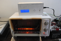 This article describes the modification of a domestic oven for reflowing printed circuit boards. To avoid re-inventing the wheel I’m using firmware from another project, the Hobbybotics reflow controller. It has everything you’d expect from a reflow oven converter such as PID temperature control and solder profile selection and is nicely documented so it should be easy to reproduce. And it has a PC application as a bonus.
Hardware
I was in dubio if I would either re-use the Hobbybotics PCB as-is, modify it to my needs, or build the circuit on protoboard. I did not need quite a few of the features on the board (RS-232, Real Time Clock, break-out headers for the pins etc).
At first I attempted to make a PCB from the original Hobbybotics design. I printed the PCB design on laser transparency sheets, transferred it to a pre-sensitized board using a UV face tanner, and etched the board. The traces in the original design are not very wide and my board suffered from severe under-etching.
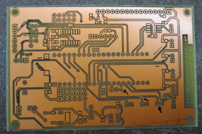
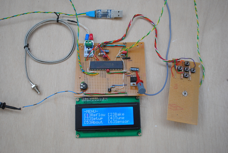
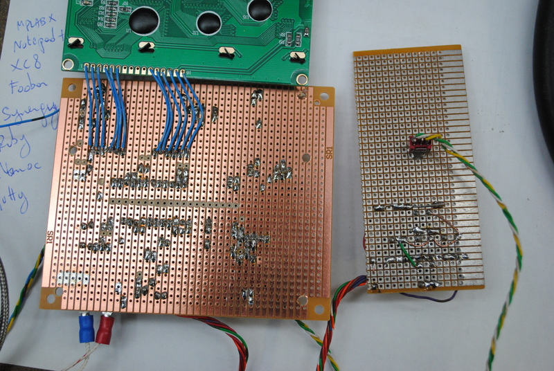
I didn’t want to touch up the board design since it was made in the crappy ExpressPCB, so I started to re-build the board in Eagle CAD. I soon decided that it wasn’t worth the effort since the basic circuit is quite minimal anyway. So I built it on protoboard. I took it step by step so I could troubleshoot any problems while building the circuit. First I soldered in the 16F877A, the oscillator circuit and the ICSP header, and checked if I could program the microcontroller and if it was oscillating. Then I built the power circuit using a 7805 regulator, and checked it I had a clean 5V on the power rail. Then I built the LCD circuit, and checked if it displayed the menu. Then I added the buttons and switch and tested them. Lastly I added the thermocouple and USB modules and tested them.
Microcontroller
The original firmware uses a PIC 16F877A. I decided to use the firmware as-is, and had the 16F877A in my parts bin in quantity.
Temperature
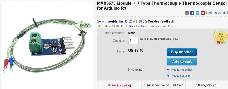
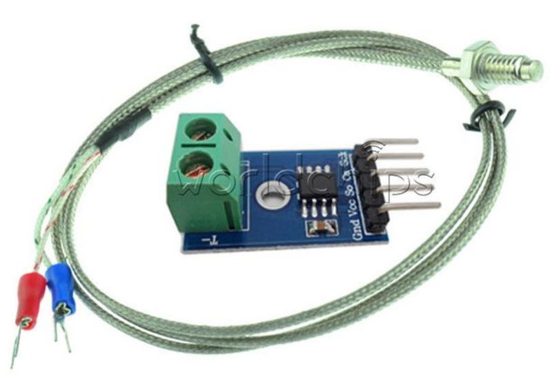
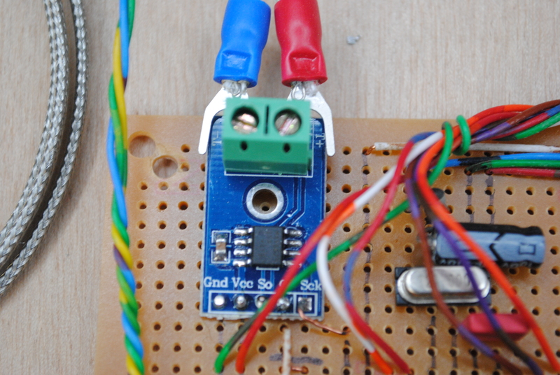
To read the temperature of the PCB in the oven, I used an existing breakout board for a MAX6675 thermocouple interface IC. This IC reads the voltage on the thermocouple, compensates for the cold junction temperature, and outputs the temperature over an ISP bus. [](/assets/Solder reflow oven/Clipboard04 thumb.jpg)
For convenience I bought a ready-made module on eBay. The module I bought included a K-type thermocouple.
Oven heat control
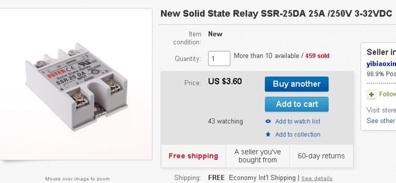
To control the temperature of the oven, the microcontroller drives a solid state relay which switches the oven’s heating element on and off using PWM. The PWM rate is PID-controlled by the microcontroller.

I bought the SSR on eBay again. The Fotek brand is one of the cheapest you’ll find, but do mind that they do not perform well in the thermal department. I have melted one before in my automatic brewing system. So make sure to properly heat sink them and not run them at high current for prolonged periods of time.
The reflow oven is typically on for only a few minutes at a time, so for this application a cheap Fotek will do just fine.
Display
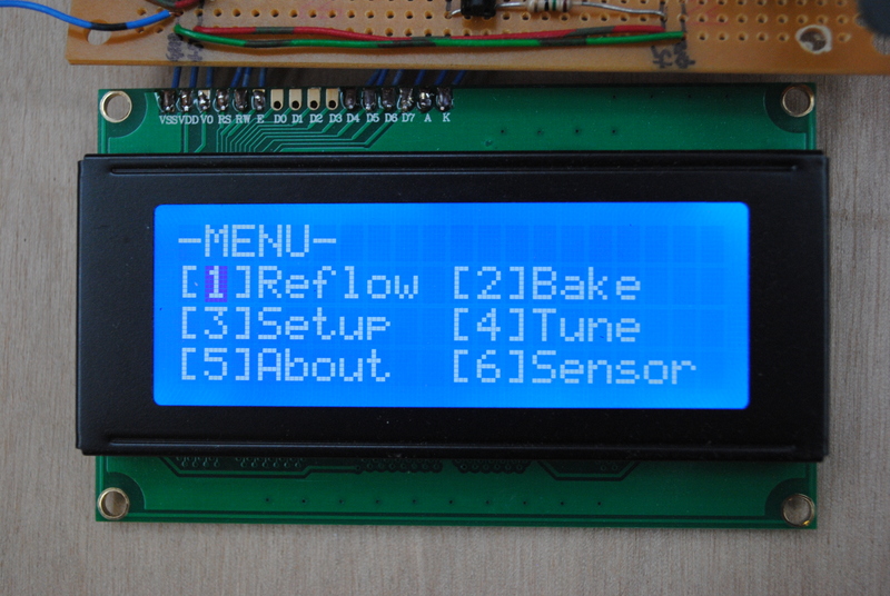
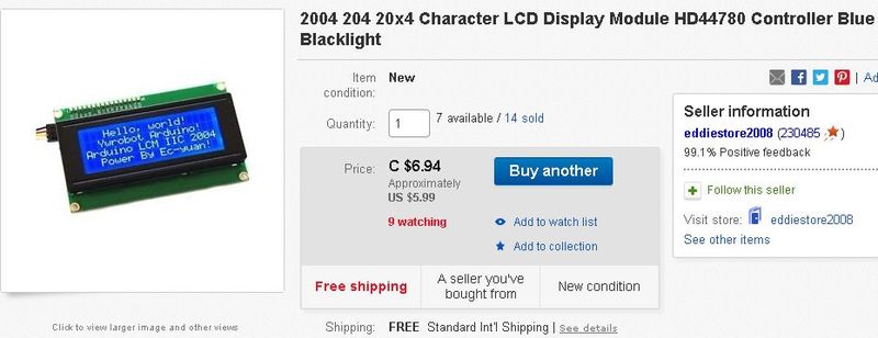
The oven’s status and settings are displayed on a 4-line 20 character LCD display. I sourced one with a blue backlight from eBay. In just a few years this will look nice and vintage.
USB connection
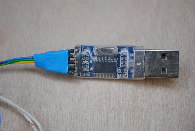
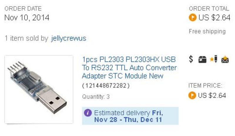
The microcontroller can be connected to a host application running on a PC over USB. To convert the microcontrollers’ TTL levels to RS-232 levels I’m using a ready-made TTL-to-USB converter. Again sourced from eBay.
Putting it all together
As mentioned I mounted all components on a piece of protoboard and soldered it together.
Firmware
The firmware is the stock Hobbybotics Reflow Controller V8.03 firmware.
Oven
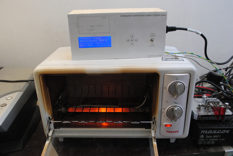
To heat the PCB’s I have acquired a small second-hand toaster oven. It is a 7L 750W model with a ceramic heating element on the top and the bottom. Early tests showed that the oven wasn’t able to ramp up the temperature fast enough, so I removed the metal covers protecting the heating elements, but which were blocking much of the heat radiation. Without them, the oven performs fine.
Two modifications are necessary to the oven. Firstly I bypassed the mechanical timer so that the oven is always on. This is simply a matter of bridging the input and output connections of the timer. Do mind that an oven designed to reach soldering temperatures is not the best place to use soldered connections, so I used crimp wires.
Next I needed to hook up the oven to the SSR. Since the oven is getting quite hot, and there isn’t much room, I decided not to integrate the controller and SSR into the oven but constructed a separate controller box. The SSR is integrated into this box, and to connect the oven I simply cut off the power plug and connected the power wires to the incoming power to the controller box. The SSR sits in series with the phase wire to the oven.
Control box
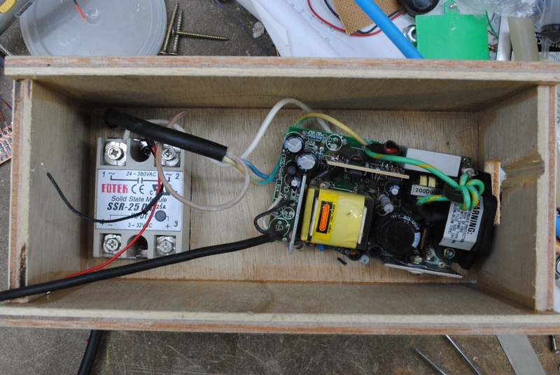
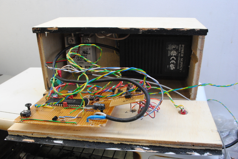
I whipped up a quick wooden box on my table saw slide. I installed a gutted switching power supply in the back of the box. I also mounted the SSR to the back side. A heat sink protrudes through the back to cool the SSR.
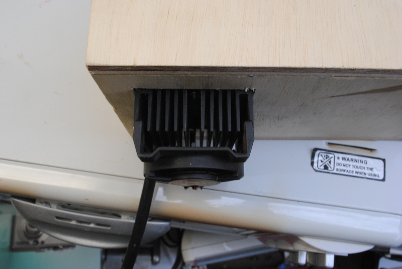
The heat sink is an old Pentium 1 heat sink from my scrap bin. It has a matching clip-on fan which I powered from my 12V supply rail. The fan is probably unnecessary, but I think it’s a neat recycling opportunity.
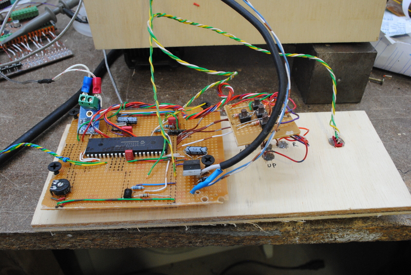
The rest of the controller electronics are mounted to the front panel behind the LCD. During testing I had already mounted some buttons to a piece of protoboard, but this didn’t turn out to be a convenient way of mounting them, so I just drilled 5 holes for some new control buttons, wired them up in parallel with the old buttons, and glued them in. The buttons will sit behind my front cover and thus form membrane switches.
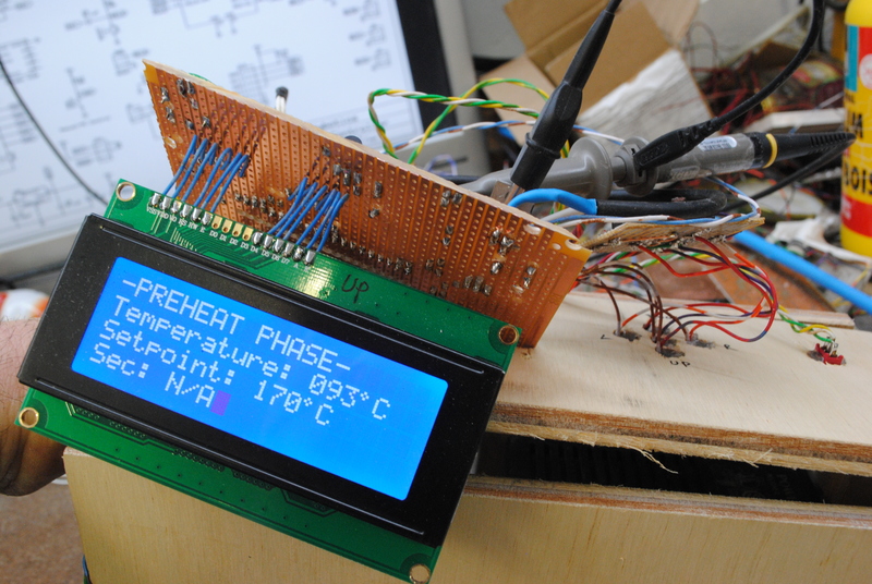
The display was mounted with 4 screws to the protoboard, and recessed into an opening in the front panel.
After completing the wiring and testing I fitted the front panel into the box and screwed it shut.
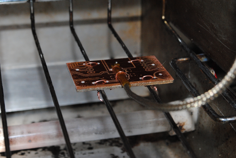
Inside the oven I have mounted the thermocouple on a piece of “sensor” PCB. This essentially allows the thermocouple to measure the temperature of an actual piece of PCB material in the oven, instead of just the air temperature. I insulated the end of the thermocouple with some Kapton tape, leaving the tip exposed and in contact with the PCB.
I made a front panel for the controller box in Visio, and after laminating it, glued it onto the front.
Controller settings
PID loop
I am running my PID loop at the following setting:
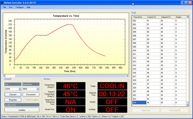
P: 150, I: 2, D: 2, cycle: 2
Solder profile
I seem to get good results with my solder paste using the following solder profile.
Soak: 160 C, 90 sec
Reflow: 220 C, 30 sec
Cooldown: 45 C, 0 sec
Results
This is the soldering curve I get with my oven. Ideally the oven would ramp up the heat faster, but it works ok.

Resources
- Application
- Source code and HEX file
- Firmware listing
- PCB
- Schematic
- GitHub files
- PCB and schematic in ExpressPCB format
- My unfinished attempt to migrate the PCB and schematic to Eagle
- Front panel design (Visio)
- Solder profile log (CSV)