Dissecting the Hasselt firmware
 The firmware for the Mespelare board will be based on kurtsidekick’s Hasselt firmware. To gain a good understanding of how this firmware works, we will dissect it in detail in this article.
We’ll be doing this in a methodical way, starting from the main() function, and investigating each function as we go. We’ll also document the program flow in a diagram so we can keep track of the calls between the different functions.

Learning the way existing code works is much easier when you can have insight in the code as it runs. While we can’t really look inside a running microcontroller the way we can with programs on a computer, we can use the serial port to send us information on the running code (values of variables, if statement conditions, signal specific points in the code etc). The article Adding serial debugging describes how to add some basic serial debugging capability to the Mespelare module.
That being said, let’s take a look at how the code works. We’ll take it from the top in main.c
Includes
The following header files are included, they contain code which we’ll describe below.
#include <p18cxxx.h>
includes the p18f45k80.h processor header for PIC18F45K80
#include <timers.h>
Microchip standard library header file for using the timer peripheral.
#include "/common/eeprom.h"
EEPROM access routines.
#include "/common/can18xx8.h"
PIC18CXX8 CAN C Library Header File by Microchip. Low-level CAN driver code, including CANInitialize(), CANSetOperationMode(), CANSetBaudRate(), CANSendMessage(), CANReceiveMessage(), and others.
#include "can18F66K80.h"
CAN library by Ake Hedman, declares the function prototypes for a bunch of vscp18f _ functions.
#include "/common/vscp_firmware.h"
VSCP firmware stack by Ake Hedman.
#include "/common/vscp_class.h"
Contains the definitions for the available VSCP class id’s.
#include "/common/vscp_type.h"
VSCP Level I/II type definition file .
#include "VSCP_node_defines.h"
This is an interesting file which contains configuration data for our node’s hardware. The following things are set here:
- Firmware version
- _Timer0_ timeout value (= overflows every 10ms)
- Pin defines for the hardware input and output pins
- Locations where VSCP registers are stored (in EEPROM)
- Values for some macros (button operations such as pressed, released, hold, output actions such as NOOP, ON, OFF, TOGGLE, PWM, relay control bits etc)

#include "main.h"
Defines a bunch of variables used by the VSCP libraries and sets their startup values.
Low priority interrupt
Declared as:
#pragma interruptlow isr_low
void isr_low(void)
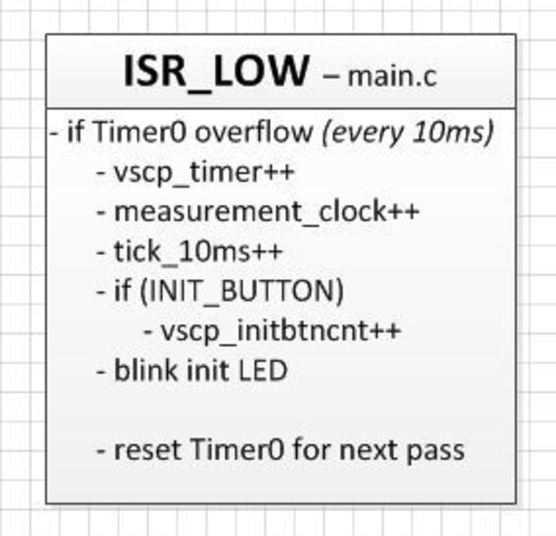
This interrupt is used to test if Timer0 has overflown. Every time this happens (every 10ms), the following actions are taken:
- vscp_timer++
- measurement_clock++
- tick_ms++
- check if the INIT_BUTTON is held (to start node cold boot process)
- service the VSCP status LED on the node (blinks when acquiring node address, steady if node is active)
- reset Timer0 for the next pass
High priority interrupt
Declared as:
#pragma interrupt isr_high
void isr_high (void) {
This interrupt is apparently used “to temporarily test audio generation”. It inverts pin C0 every time the interrupt is triggered. I tested this pin with my scope and don’t see any waveform (pin is kept low), so I guess the interrupt isn’t enabled in the rest of the code.

main() function
As the microcontroller starts up, it first runs the main() function. This is our entry point into the code.
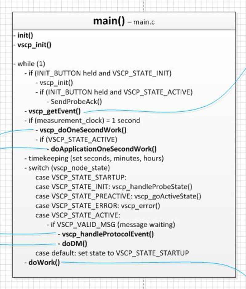
The main() function calls the vscp_init() function and then goes into an infinite loop (while(2)), in which the following actions are taken:
- feed the watchdog timer
- check the INIT_BUTTON, if the node is in VSCP_STATE_INIT and the init button is held, set the node’s nickname as VSCP_ADDRESS_FREE and start the node initialization process (_vscp_init())
- get a new event from the bus (vscp_getEvent()_)
- every second (measurement_clock value is >100 times a 10ms tick), call vscp_doOneSecondWork(), and if VSCP_STATE_ACTIVE call doApplicationOneSecondWork() as well
- do some housekeeping on the seconds, minutes and hours variables
- check the VSCP state of the node (vscp_node_state):
- if the node has been freshly started (VSCP_STATE_STARTUP, meaning a reset or power-up): if the node has no address yet (VSCP_ADDRESS_FREE), set the state to VSCP_STATE_INIT, else set state to active
- if the node is in the init state (VSCP_STATE_INIT), assign a nickname (vscp_handleProbeState())
- if the node is waiting for host initialisation (VSCP_STATE_PREACTIVE), call vscp_goActiveState();
- if the node is active (VSCP_STATE_ACTIVE), check if there is an incoming and valid message; if so then process it (vscp_handleProtocolEvent()), and run the Decision Matrix on it (doDM())
- if the node is in error state (VSCP_STATE_ERROR), call vscp_error()
- at the end of the main function, doWork() is called and then the infinite while-loop returns to its begin
vscp_getEvent()
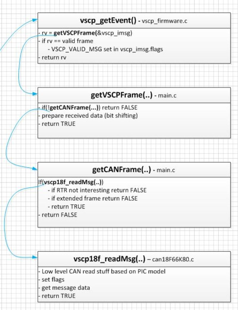
Here’s how the firmware gets its events:
- the main() function calls vscp_getEvent().
- vscp_getEvent() gets a frame from getVSCPFrame() and then checks if the received frame is valid. If so, it sets a flag in the vscp_imsg.flags variable of that frame.
- getVSCPFrame() calls getCANFrame() and prepares the received data through some bit shifting
- getCANFrame() calls vscp18f_readMsg(), checks if it is a frame of interest and is not an extended frame.
- vscp18f_readMsg() does the actual low level read of the CAN bus, gets the message data and sets the flags.
In the end the received event is in the variable vscp_imsg, which is a struct with the following members:
uint8_t flags; ///< Input message flags
uint8_t priority; ///< Priority for the message 0-7
uint16_t class; ///< VSCP class
uint8_t type; ///< VSCP type
uint8_t oaddr; ///< Packet originating address
uint8_t data[8]; ///< data bytes
vscp_doOneSecondWork()
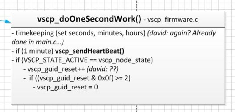
This function does the following:
- some housekeeping on the seconds, minutes and hours variables. I don’t quite understand why it is necessary to do it again, as it is already done in main(), but perhaps I’m missing something.
- every minute vscp_sendHeartBeat() is called, so that the node sends out a heartbeat event to signal it is still alive.
- if the node state is active (_VSCP_STATE_ACTIVE), a bit of kung-fu is done with the vscp_guid. I currently don’t understand yet why.
doApplicationOneSecondWork()
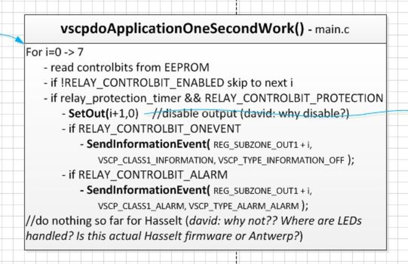
In this function, the actual application functionality is implemented. The functionality of the Hasselt node is limited to sending input button events and act upon events to set output pins based on received events and the Decision Matrix. Sending the input button events is handled elsewhere (xxx where?), asserting the outputs is done here.
This function does the following for each of the 8 outputs (0-> 7):
- read its control bits from the corresponding register stored in EEPROM
- if the output is not enabled, do nothing and skip to the next output
- call SetOut() which disables the output. I don’t quite understand why, and where the outputs are enabled again. This effectively means that all active relays are switched off every second. (xxx).
- if the RELAY_CONTROLBIT_ONEVENT control bit is set, send an information event OFF
- if the RELAY_CONTROLBIT_ALARM control bit is set, send an information event ALARM
SetOut()
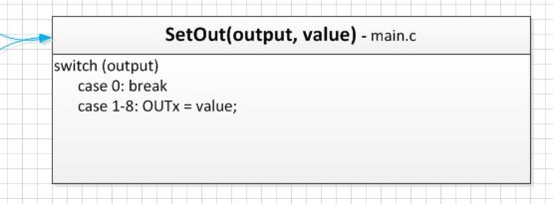
This function takes two arguments: the number of the output it should set, and the value which should be set. It then sets the OUTx variable to that value. OUTx are defined labels for the PIC’s latch registers LATybits.LATyx.
.. to be continued..