Mespelare VSCP node
The Mespelare node is a VSCP board based on the Hasselt board by kurt_sidekick, used to read a Niko 6-way potential-free button set, and control it’s 6 indicator LEDs as well as 6 outputs (teleruptors).
It is intended to serve as a general base node for further development of custom functionality, without each time having to re-invent the wheel. To reach this goal most processor pins are broken out to pin headers, which either connect to the Niko 6-button switch and teleruptors, or are populated with pin headers so another board can be piggy-backed onto the base node (Arduino shield-style). Using the same base board to build new applications on offers the following advantages:
- A stable, well-debugged and known-working base platform
- The possibility to do bigger board production runs
Features#
The Mespelare VSCP board has the following features.
7 inputs#
6 inputs are intended to read the button-presses on the Niko 6-way push-button set. A seventh input was added just because we can, and to provide an extra input in case the base board is used in another application. The inputs are filtered using a low pass filter on each channel to prevent HF interference from reaching the microprocessors’ inputs.
2 x 7 outputs#
6 outputs are in are intended to control the LEDs that are integrated in the Niko 6-way push-button set. A seventh output was added just because we can, and to provide an extra output in case the base board is used in another application.
6 outputs are in are intended to control up to 6 teleruptors. A seventh output was added just because we can, and to provide an extra output in case the base board is used in another application.
One wire interface#
The micro-controller’s OneWire interface was broken out onto a pin header.
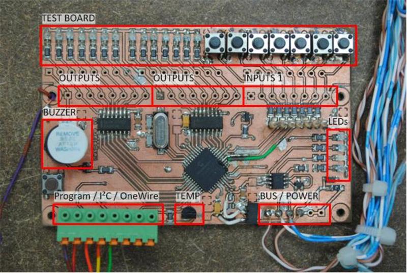
On board peripherals:#
- 1 button (which can be used as a VSCP button or for troubleshooting)
- 1 LED (mainly for troubleshooting purposes)
- Buzzer (mainly for troubleshooting purposes)
- A footprint for a DS18B20 temperature sensor.
On board status LEDs:#
- RX (CAN bus)
- TX (CAN bus)
- Power status
- Status (VSCP)
Power supply#
- On-board Microchip MCP1804 power regulator
- 6.3-28V input
- 5V 150mA output (the low power output means extension boards will require a separate regulator)
- Protected by a 200mA poly-fuse and crowbar circuit
- Filtered against power rail noise
- Proper decoupling for all chips on the board
CAN bus#
- A properly filtered, protected and impedance-matched bus connection
- Controlled by a Microchip MCP2551 bus interface chip
Expansion / ICSP header#
A single “expansion/ICSP header” combines the ICSP signals with a OneWire and I²C bus. The order of the first 5 pins on the header are compatible with the PICkit pin-out.
PCB mounting#
4 mounting holes in the corners for easy mounting, M3 size.
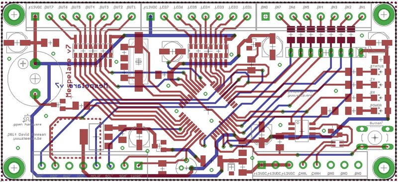
Printed circuit board#
Design criteria#
- Possible to produce at home using a photo-transfer process, so that the board can be prototyped and tested at home. This means:
- PCB size must not exceed Eurocard dimensions
- a minimum of via’s
- no tight spacing of components and tracks
- a minimum of through-hole soldering on the top layer
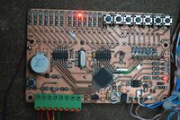
- Addition of an integrated set of LEDs and buttons on the first prototype
I had the PCB professionally produced at SeeedStudio, it cost only 1.83€ per board for 30 boards shipping included.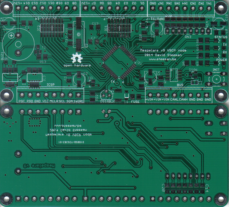
Testing#
Until we write custom firmware for this node, we’ll be testing the node bit by bit.
Quick test#
Although the firmware for the Hasselt node isn’t compatible with the pin-out used by the Mespelare node, some functionality does work. If you load the Hasselt hex file the node will be visible on the bus. Buttons 1 will send events as well.
Hardware tests#
I use these detailed test programs to check separate parts of the hardware to see if they function correctly. Download a zip with the source code and pre-compiled HEX file.
- Blink-a-led : generates a buzzer tone at start-up, and then randomly blinks all LEDs on the board
- Button & leds: each press of the init button toggles each LED on the board, one after the other
- Inputs : toggles the corresponding outputs when pushing a button
- CAN toggle : puts a 50Hz square wave on the CAN bus pins
- DS18B20 Onewire : beeps the beeper when a temperature change is detected
- DS18B20 Onewire serial : outputs temp value to serial (9600, 8n1, no flow), and beeps the beeper when a temperature change is detected
- Button : sounds the buzzer when the misc button is pressed (board revision v6 only)
Downloads#
Source code: see the article Mespelare VSCP firmware - first compile