Mespelare proof-of-concept
Before putting the Mespelare board into production, I wanted to do a final proof-of-concept test to make sure the hardware design is 100% correct before ordering the boards and components. I wanted my first professional production PCBs to come out 100% perfect, I would hate it to have to bodge up 30 boards…
Hardware#
Changes#
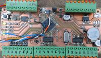
To fix the mistakes I learned from testing the Mespelare v6 board, I made another prototype, Mespelare v9.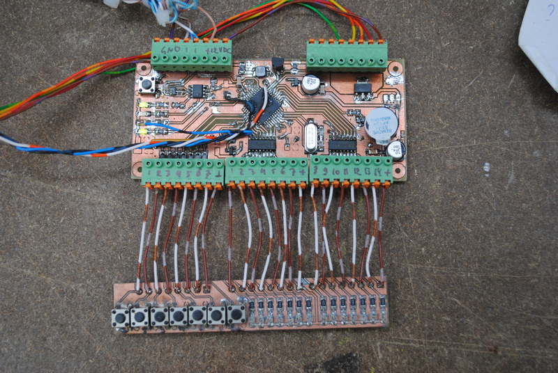
This design incorporates the following changes:
- Changed pin assignments, mostly because I used pin RA4 in v6, which isn’t available on the 18F45K80. Another lesson in reading the datasheet.
- Added a capacitor to pin 23 as per the datasheet.
- Changed the drill hole diameter to 2,2mm.
- Added a second 12V power regulator so I can increase the bus voltage to 24V DC to minimize voltage drop effects.
- Corrected the footprint for L2, in v6 it was too small.
- Changed the footprint for the solder bridges under the ULN2003’s, so that they can be easily bridge by a drop of solder if the board is not populated by a ULN driver.
- Added ‘flyback’ diodes for both LDO’s to protect against short-circuit of the power bus, as per the datasheet.
- Added VSCP logo to the PCB design.
- Added a larger pad for the TX pin so that a wire can be soldered on [for debugging purposes](/posts/Adding serial debugging/).
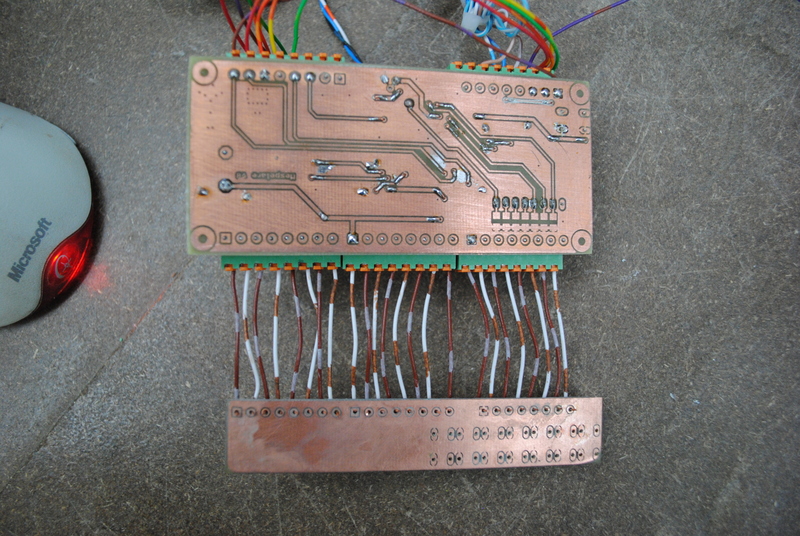
The PCB design was printed on a transparent laser sheet, transferred to a pre-sensitized PCB using a UV face tanner, developed in drain cleaner (NaOH) and subsequently etched. I populated the board by hand.
Testing#
The hardware was tested using the test files made for the v6 board. Obviously a new pin_defines.h file was used to reflect the hardware changes.
Firmware#
The firmware needed to be adapted for the changes made in the hardware (mostly changing pin assignments). It was then tested for correct functionality:
- short circuits between power rails and ground
- bus power has correct voltage
- correct voltages on power rails
- oscillator runs
- bus communication works
- button inputs and outputs work (using a button and LED test jig)
- VSCPworks can read and write the module
- DM works as expected
Resources#
- Schematic & PCB (Eagle CAD)
- Firmware (MPLAB X & C18)
- Mespelare GitHub repository