The I400: Designing and Testing an I-Class Rocket Motor
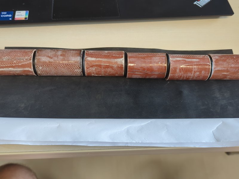
For a little over two years I have been building a rocket motor of my own: a reloadable aluminium motor, 42 mm (1.65 in) across, that burns home-made RNX-71V epoxy propellant and is designed for about 400 Ns (90 lbf·s) of total impulse. That puts it in the I class, and it is where the name comes from: the I400.
The project started on paper in September 2024. The casing and nozzle were turned in the autumn of that year, the first propellant was mixed in February 2025, and on 20 September 2025 the motor fired on the test stand. It worked, and when I took it apart the hardware could be used again as it was; only the liner and the O-rings need replacing. Since then the work has gone into making the grains better and more repeatable, and in October 2026 the next two sets of six grains came out of the moulds.
This post covers the whole thing: the propellant, the design numbers, the hardware, how the grains are made, and what the static test showed.
Why RNX#
In 2010 and 2011 we tested the Ballistic Evaluation Motor with potassium nitrate and sorbitol, the classic “rocket candy”. Sugar propellants are easy to get going with, but they are hygroscopic, they have to be melted and poured hot, and the grains soften in a warm car boot.
RNX is Richard Nakka’s family of epoxy-bound potassium nitrate propellants. The fuel and binder is ordinary laminating epoxy, so the propellant is mixed cold, cast like a stiff paste and cured in an oven at a low temperature. The cured grains are hard and tough, they don’t absorb moisture, and they can be turned on a lathe. RNX-71V is the version with 8% iron oxide:
| Ingredient | Share |
|---|---|
| Potassium nitrate (KNO₃) | 68% |
| Epoxy (West System, resin to hardener 6:1) | 24% |
| Red iron oxide (Fe₂O₃) | 8% |
| Lecithin, on top of that | 0.5% |
The iron oxide is a burn-rate catalyst. The lecithin is my addition since the autumn of 2026: it works as a wetting agent and makes the powder easier to work into the epoxy.
The propellant data I design with is the RNX-71V set from Nakka’s pages: an ideal density of 1.848 g/cm³, an adiabatic flame temperature of 1492 K and a burn rate of r = 2.573 · P^0.371 mm/s with P in MPa. At the design pressure that works out to about 5.3 mm/s (0.21 in/s). RNX burns slowly compared with sugar propellants, which suits a long, thin motor.
The design#
I designed the motor in Nakka’s SRM spreadsheet, the same tool most amateur motor builders start with. You enter the chamber, the grain geometry and the throat, and it works out the burning area as the grains regress, the chamber pressure, the thrust curve and the classification.
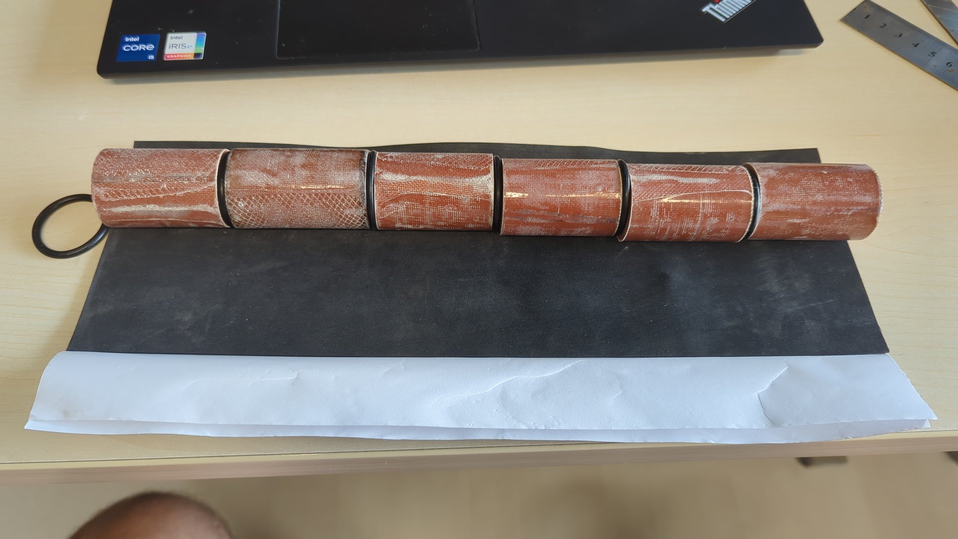
The motor carries six BATES grains: cylinders with a straight core that burn on the inside and on both ends, with the outside inhibited so it doesn’t burn.
| Grains | 6, each 32 mm (1.26 in) outside, 12 mm (0.47 in) core, 50 mm (1.97 in) long |
| Propellant mass | 364 g (12.8 oz), assuming 95% of the ideal density |
| Chamber | 36 mm (1.42 in) inside, 324 mm (12.8 in) long |
| Throat | 5.34 mm (0.210 in) |
| Nozzle exit | 16.9 mm (0.665 in), expansion ratio 10 |
| Kn (burning area / throat area) | 875 at the start, between 808 and 970 during the burn |
| Port-to-throat area ratio | 14.6 |
| Maximum chamber pressure | 70 bar (1017 psi) |
| Peak thrust | 218 N (49 lbf) |
| Average thrust | 188 N (42 lbf) |
| Total impulse | 396 Ns (89 lbf·s) |
| Burn time | 2.1 s |
| Specific impulse | 111 s |
Those performance numbers already include losses: the spreadsheet assumes 85% combustion efficiency and 80% nozzle efficiency, which is realistic for a motor this size with a turned nozzle. The port-to-throat ratio of 14.6 means the gas flows slowly past the grains at the start, so erosive burning is not an issue.
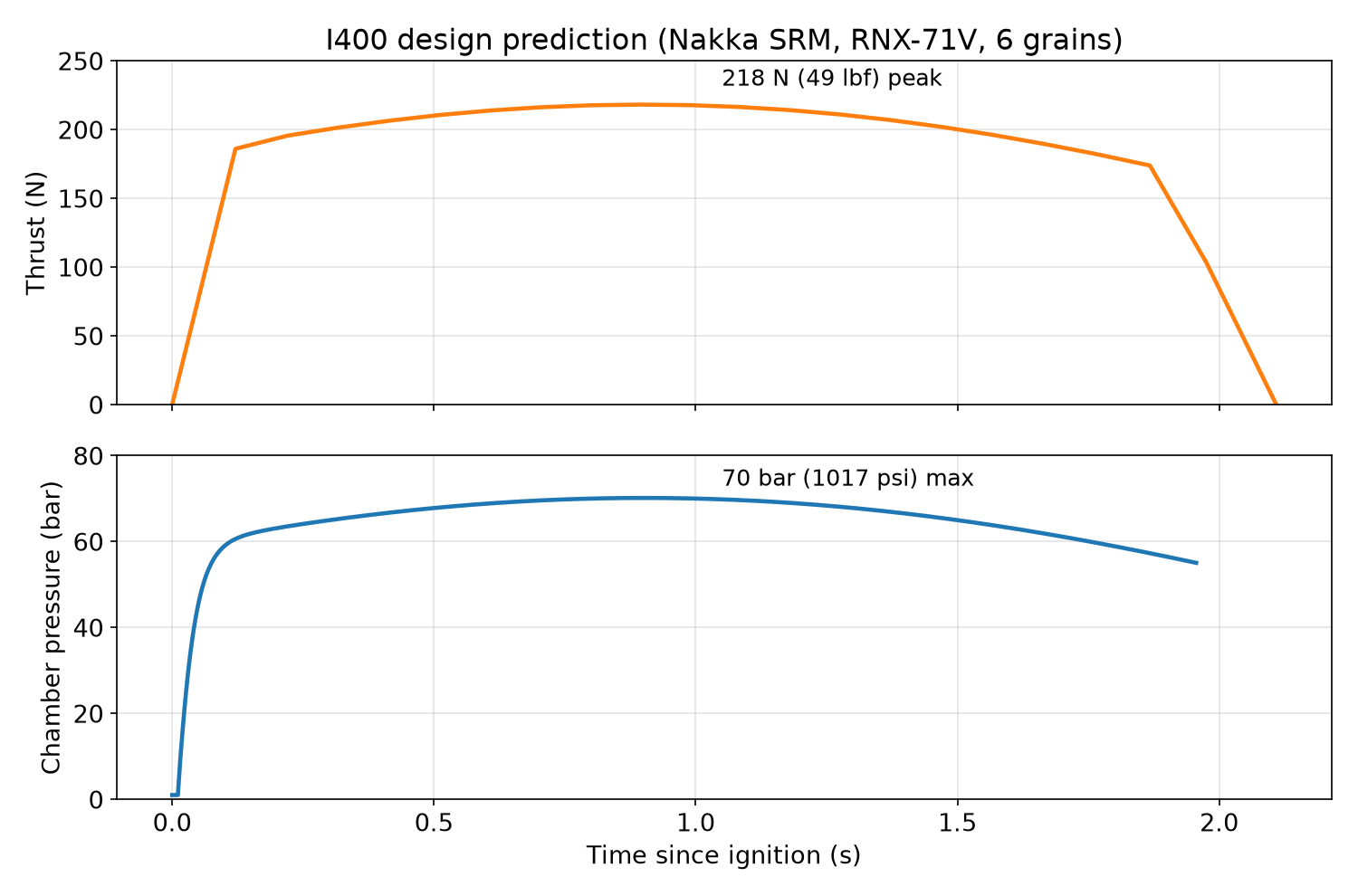
The Kn stays within about ±10% for the whole burn, so the thrust curve is fairly flat: it rises a little while the cores widen, then falls a little as the grains get shorter.
The same spreadsheet also has an 8-grain version: a 430 mm (16.9 in) chamber, 485 g (17.1 oz) of propellant, a 6.17 mm (0.243 in) throat for the same Kn and the same 70 bar, and 528 Ns (119 lbf·s) at 251 N (56 lbf) average. That one exists on paper only.
The hardware#
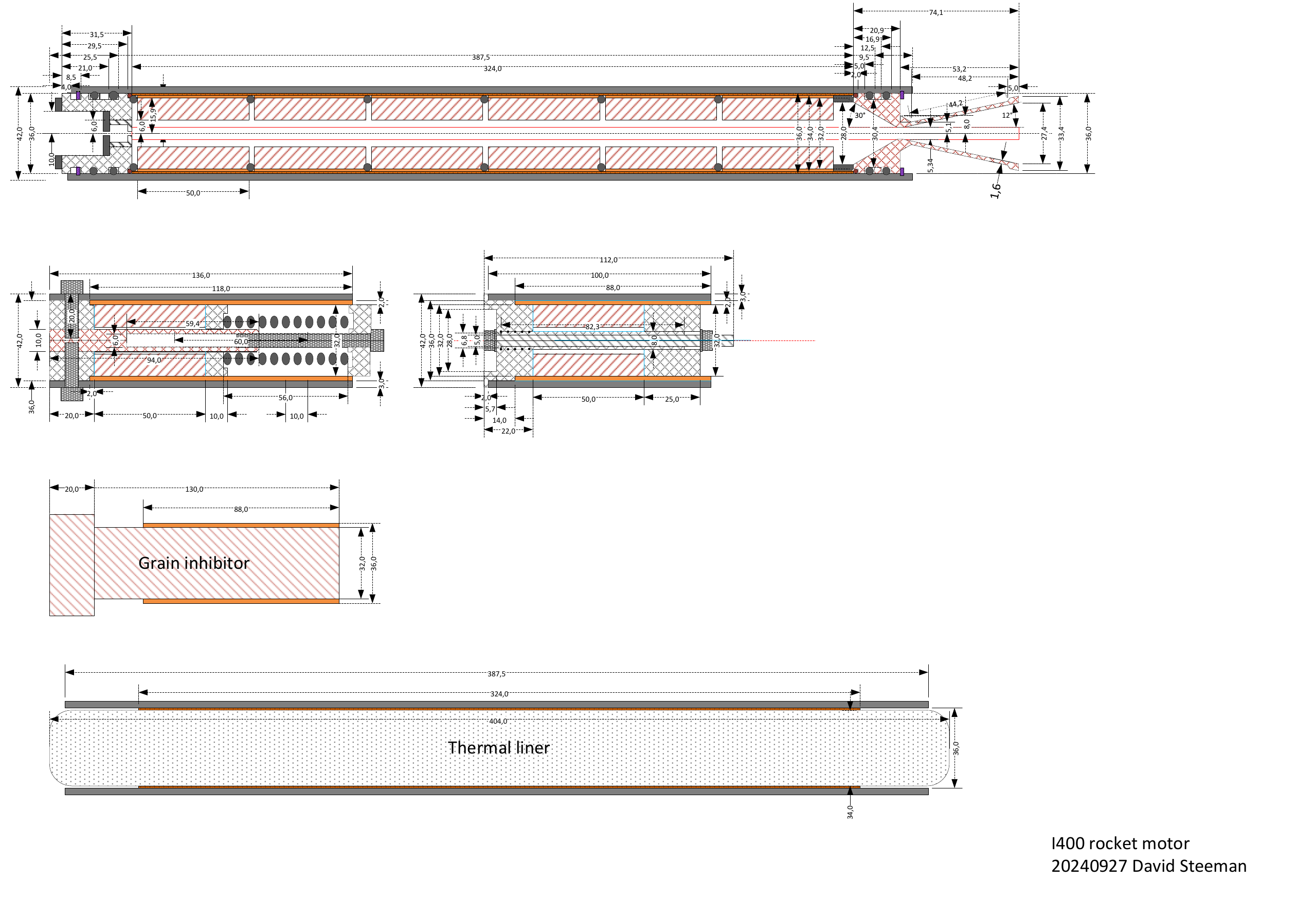
The drawing above is the one I made in September 2024, before anything was built. From top to bottom: the motor itself, two versions of the casting fixture, the mandrel for inhibiting the grains, and the thermal liner.
Casing and closures#
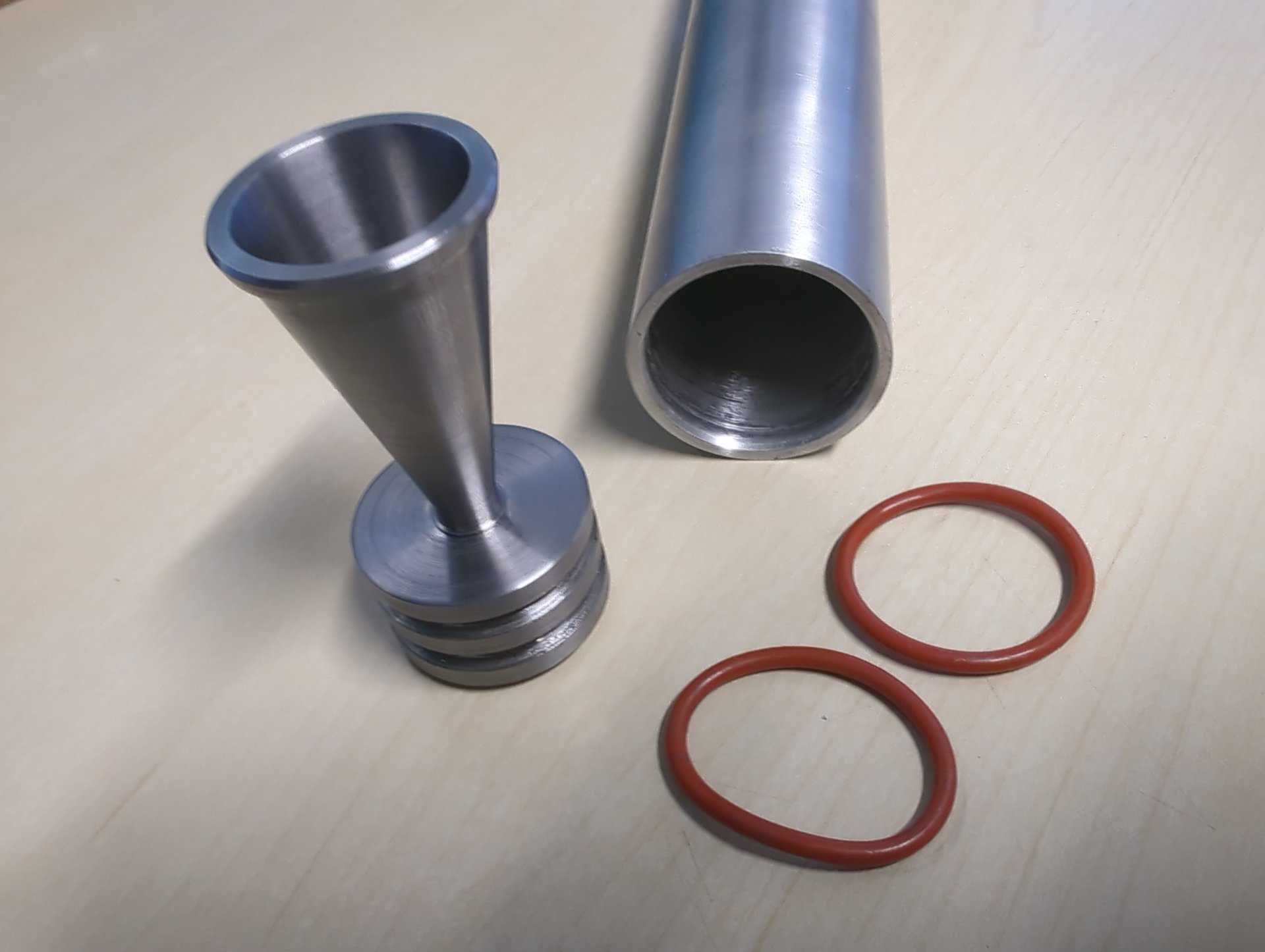
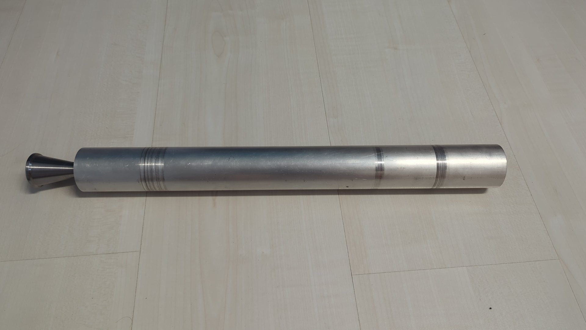
The casing is an aluminium tube, 42 mm (1.65 in) outside and 36 mm (1.42 in) inside, 387.5 mm (15.3 in) long. Both closures slide into the tube, each sealed with two O-rings and held by a DIN 472 internal circlip for a 36 mm bore, which sits in a groove turned into the tube wall. There are no threads and no screws through the casing wall: a circlip in a groove is simple to machine, and the load is spread around the whole circumference.
The forward closure has a 6 mm (0.24 in) central port. On the test stand that is where the pressure transducer connects.
Nozzle#
The nozzle is turned in one piece with its closure. It has a 30° half-angle convergent, a 5.34 mm (0.210 in) throat and a 12° half-angle divergent that opens to 16.9 mm (0.665 in). That expansion ratio of 10 is a little below the optimum the spreadsheet calculates (12 to 13 at this pressure), which costs a bit of thrust but keeps the nozzle short.
Inside the casing#
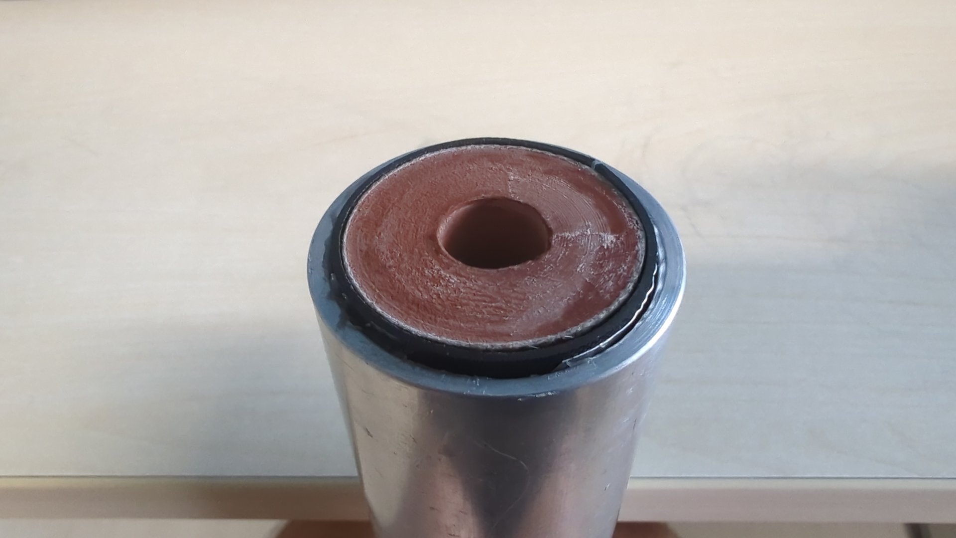
The grains don’t touch the aluminium. They sit in a thermal liner with a 1 mm (0.04 in) wall that runs the full length of the chamber, and their outside surface is inhibited with a layer of glass fibre cloth and epoxy. Between the grains are O-rings that act as spacers, so the hot gas reaches every grain end and they all burn from both ends as the design assumes.
Making the grains#
Everything is in a written checklist, because a missed step tends to show up only after the epoxy has cured. The process goes like this.
Preparing the casting tubes. Each grain is cast in a tube lined with a single layer of cardboard, laser-cut from a cornflakes box, with a laser-cut cardboard disc at the bottom. The core is formed by a rod that is greased with Vaseline and wrapped in one layer of PTFE tape, so it comes out of the cured propellant.
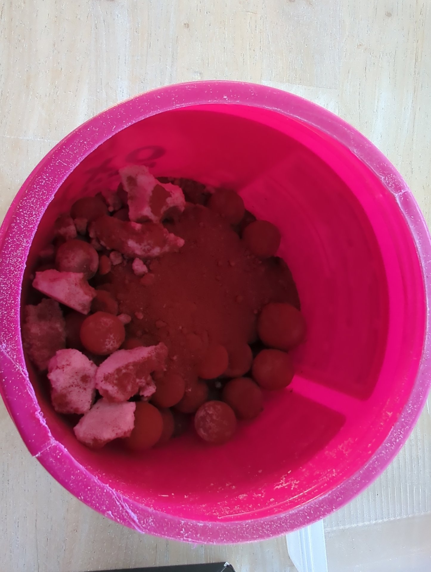
Preparing the solids. The potassium nitrate is weighed out and ground in a ball mill, then milled again together with the iron oxide so the two are mixed thoroughly.
Preparing the binder. The lecithin goes into the resin first, then the hardener. The epoxy is mixed and degassed under vacuum before the powder goes in. Air trapped in the propellant ends up as voids in the grain, and voids add burning surface that the design doesn’t account for.
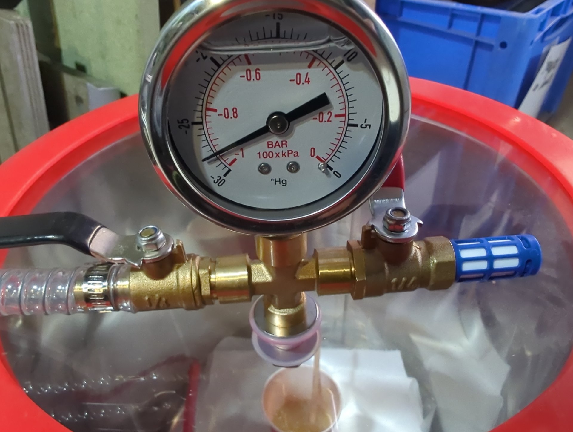
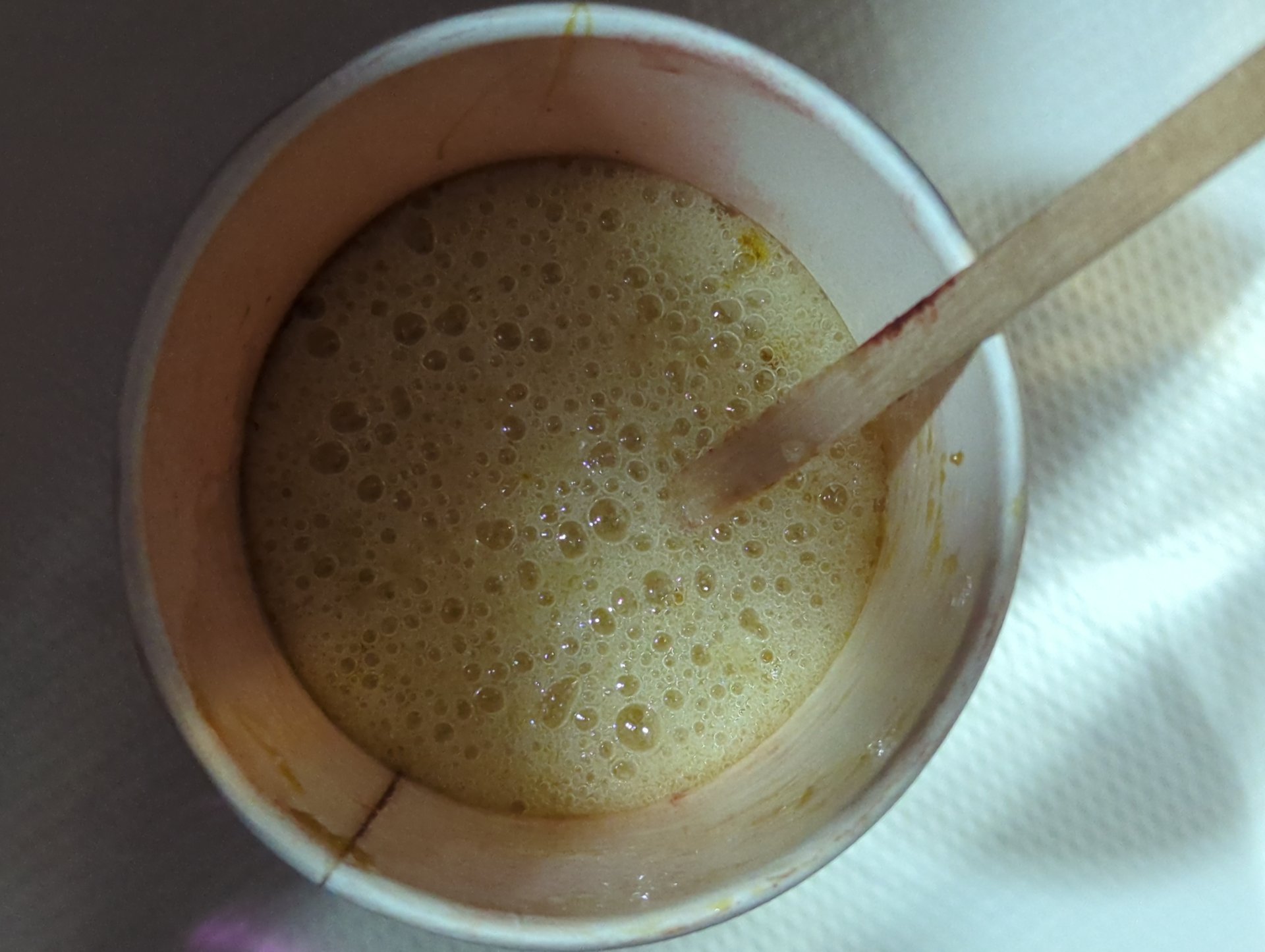
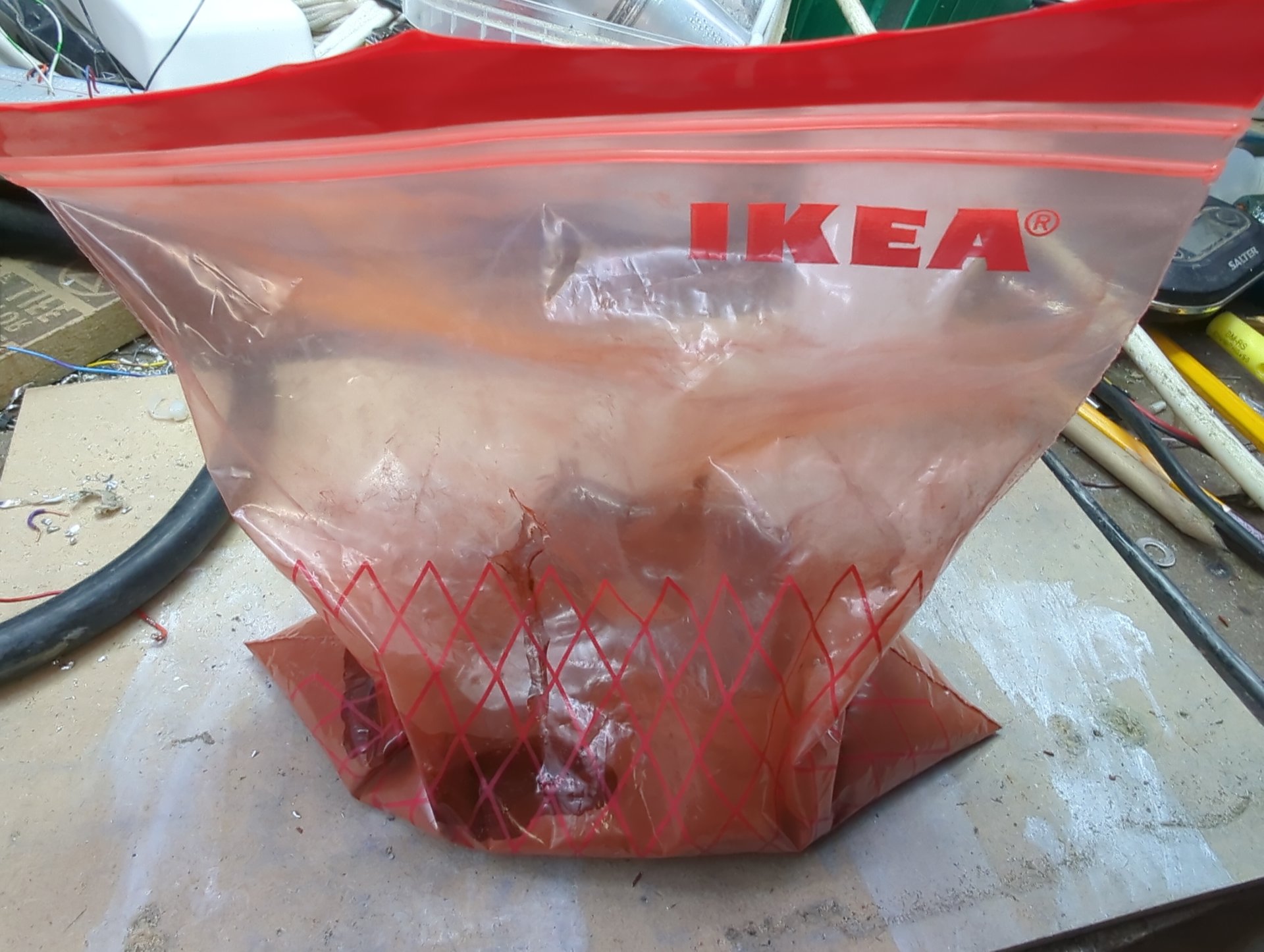
Mixing. The powder and the epoxy are kneaded together in a sturdy freezer bag. Then the bag is cut open, the propellant cut up to give it more surface, and the whole lot degassed under vacuum a second time.
Casting. The propellant goes into the tube a little at a time and is tamped down with an 11 mm drill bit. Then a plug goes on top and a threaded rod with nuts puts the grain under compression while it cures, one hour at 50 °C (122 °F).
Finishing. After demoulding, the cardboard liner is peeled off and each grain goes into the lathe, centred on its core. Both faces are turned flat until they are clean and free of voids, the outside is turned to diameter and the core drilled to size. The turnings are kept: they make good igniter material.
Inhibiting. A piece of glass fibre cloth is wetted with epoxy and rolled around the grain, then cured for another hour at 50 °C (122 °F). Back in the lathe, the grain is turned to its final diameter and length, and the core is drilled once more to remove any epoxy that ran in. Finally every grain gets a number and is weighed, so I know its actual density.
From cardboard to printed fixtures#
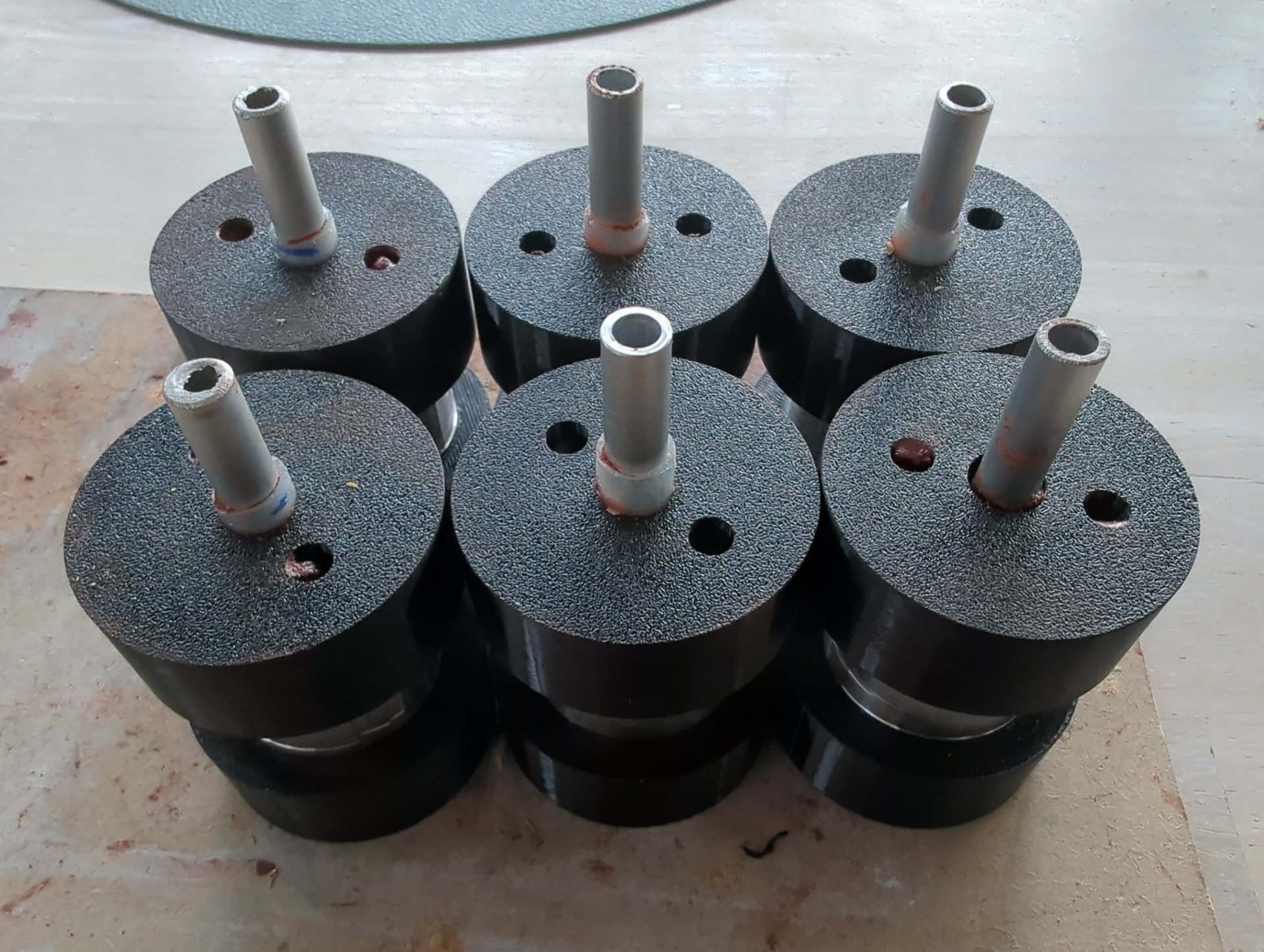
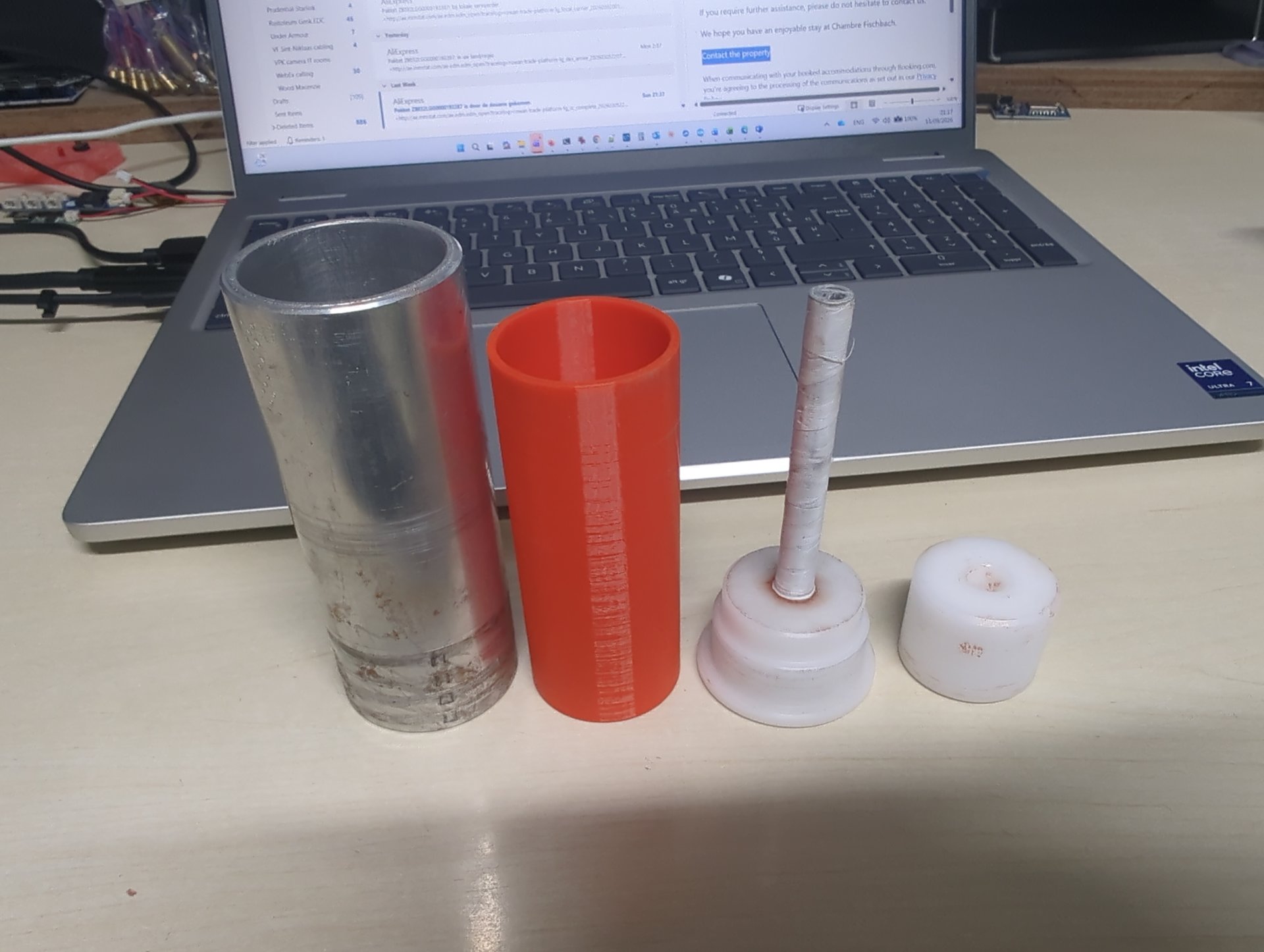
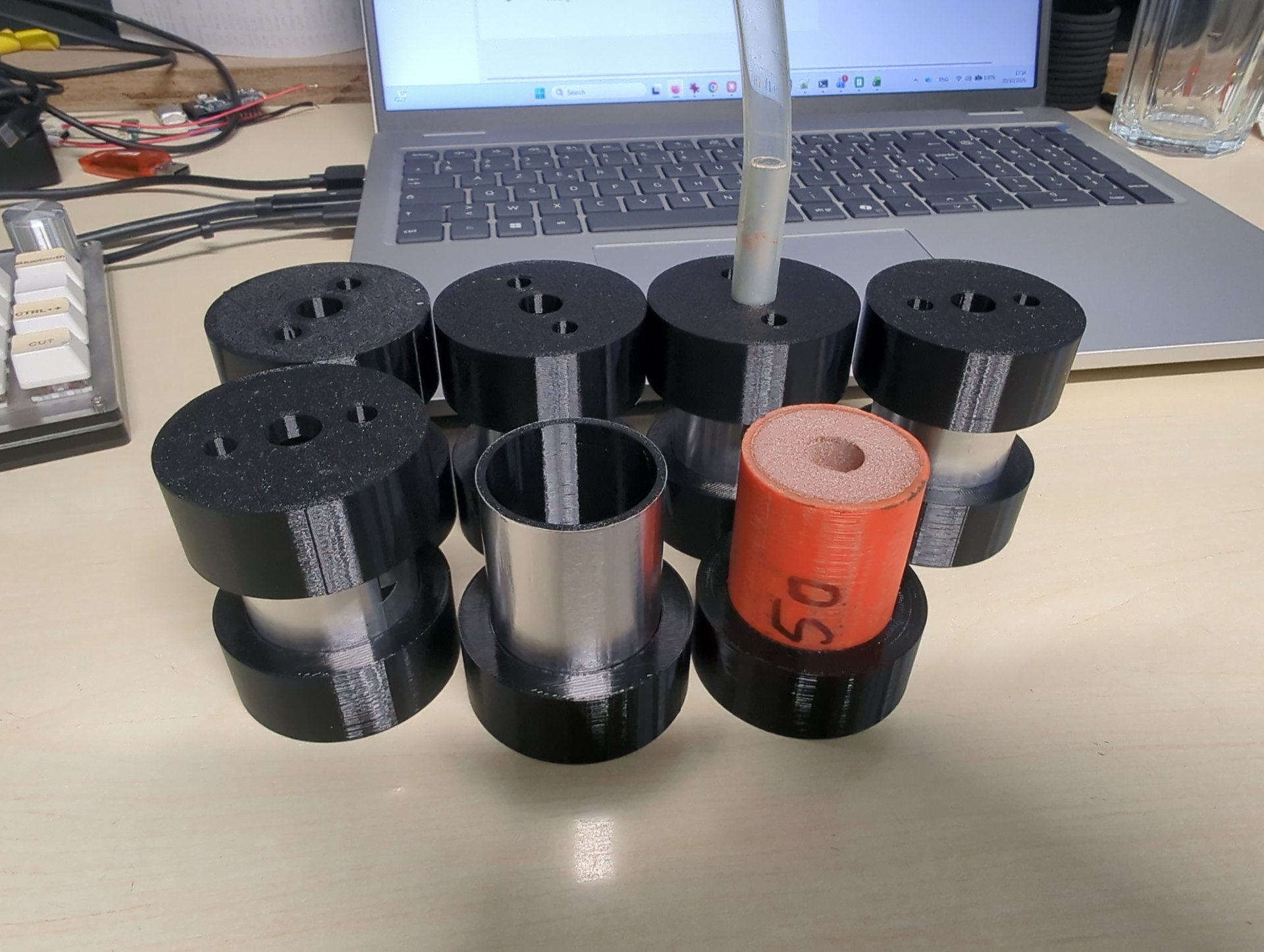
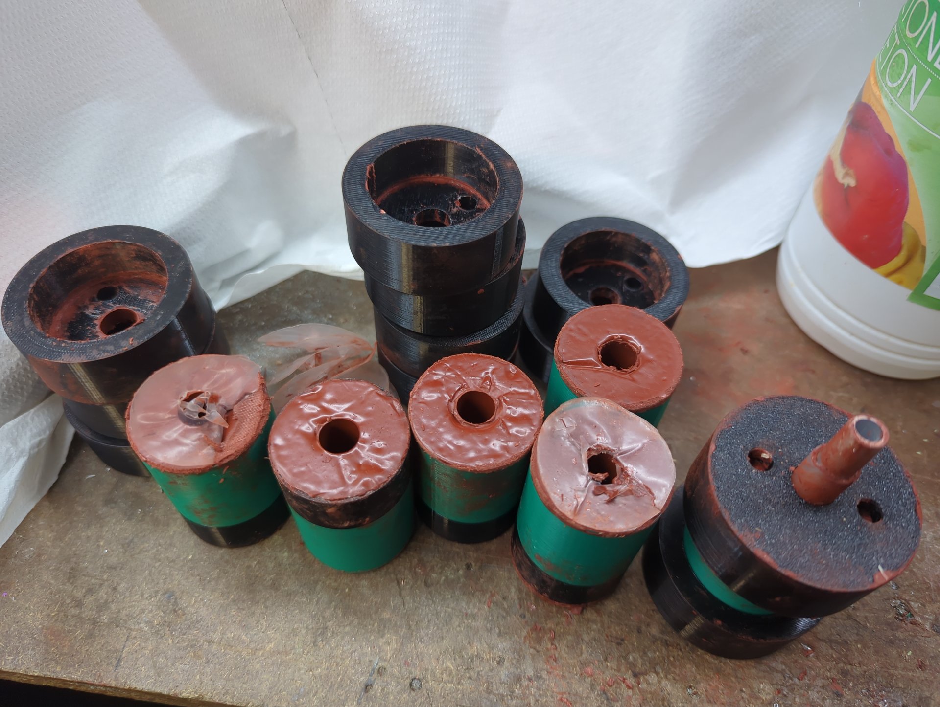
The first fixtures were aluminium tubes with plugs and core rods. In September 2026 I added 3D-printed casting tubes, and by October a set of six printed fixtures, so a full motor load can be cast in one session.
A calculator for the batches#
The first batches were weighed out with a simple spreadsheet that took the target mass and multiplied it by the percentages. Two problems showed up.
First, two batches in September 2026 were made with an old version of that sheet, which calculated the epoxy at about 19% instead of 24%. That is a big difference for an epoxy propellant: less binder means a drier mix that is harder to cast and a grain with a different burn rate.
Second, propellant gets lost along the way. Some powder stays in the ball mill and on the spoons, some propellant stays in the bag and the cup. Over three batches the milling loss averaged 6.6% of the solids, and in the one batch where I measured it, the casting loss was about 25% of the mix. A batch weighed out for exactly six grains doesn’t fill six grains.
So I built a proper calculator. You choose the formulation and the amount of cast propellant you want, and it adds the expected losses and gives the masses of KNO₃ and Fe₂O₃ to weigh in. After milling you weigh what is actually left of the solids, and the sheet scales the resin, hardener and lecithin to that, plus 2.2 g for what stays in the mixing cup. That keeps the epoxy at 24% of what actually goes into the grains. Every batch goes into a log with the weights, the losses and notes.
The two six-grain batches of October 2026 were both a little short: the sixth grain only just filled, and the second time I had to scrape a lot of propellant from the sides of the bag. The casting loss is the number to raise for the next batch.
The static test#
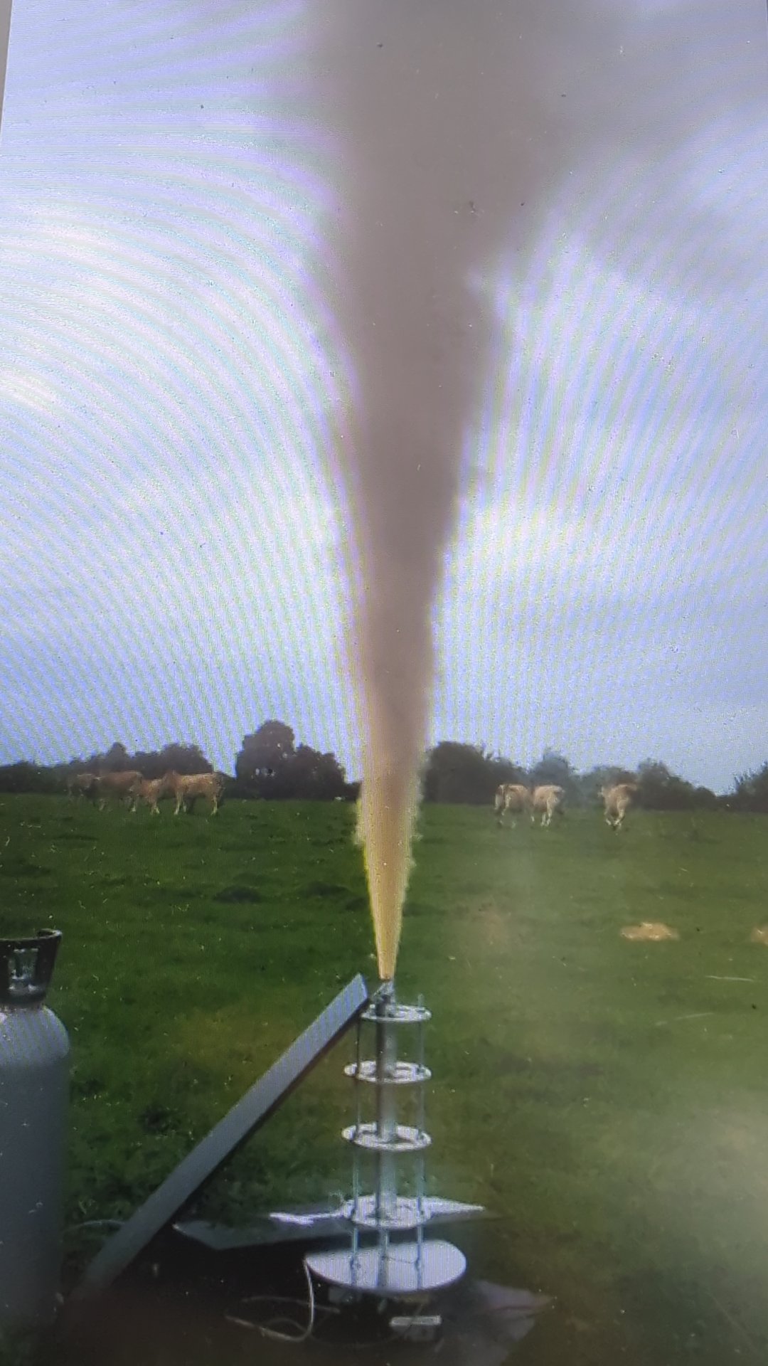
On 20 September 2025 the I400 fired on the test stand. The motor stands upright with the nozzle on top and pushes down on a load cell, guided by a set of rings on threaded rods. Chamber pressure is measured at the forward closure, and a break wire runs through the motor.
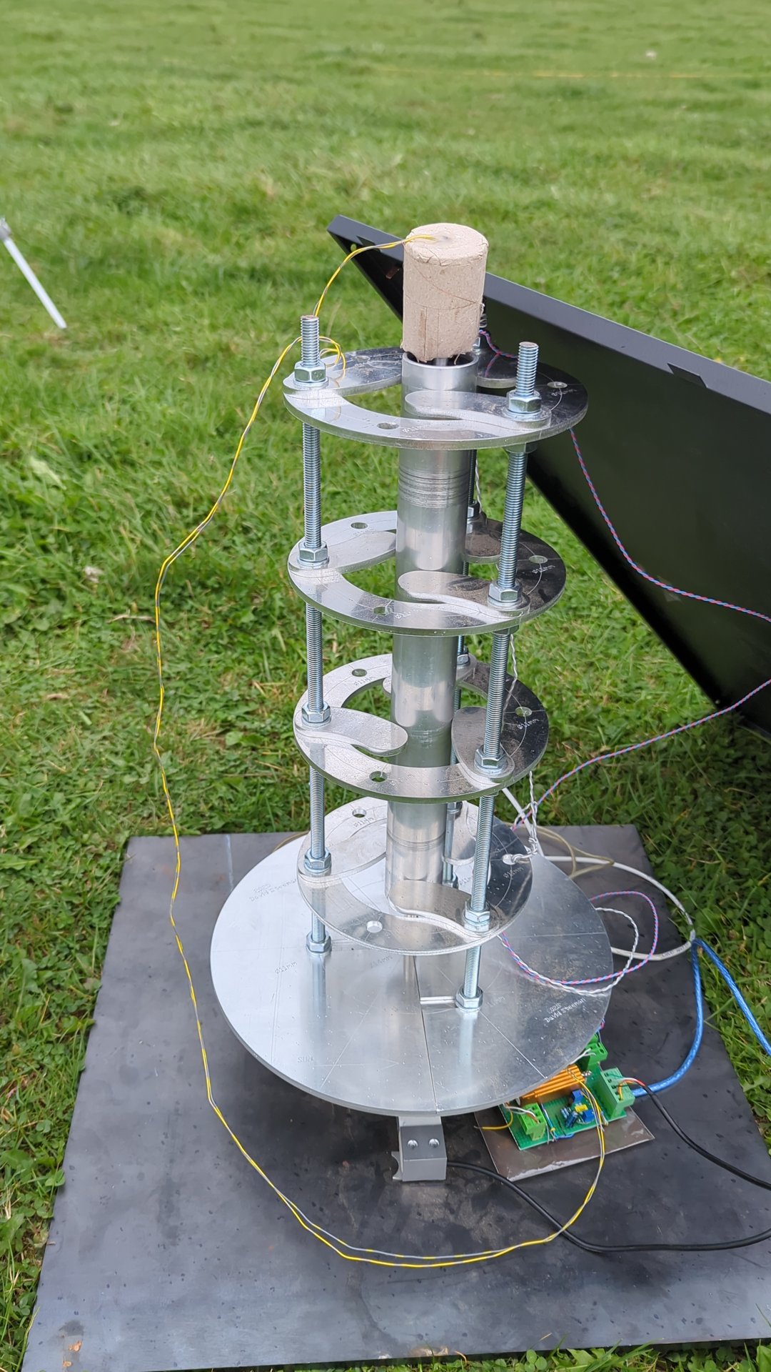
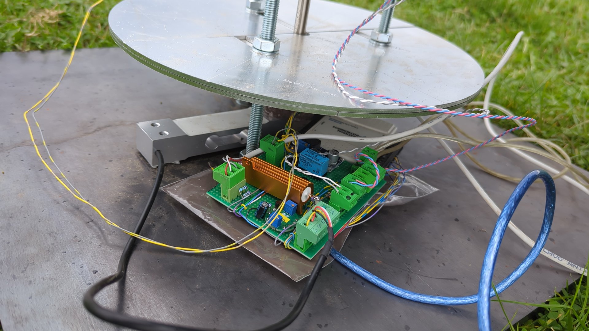
The data was logged at 1000 samples per second with the NI USB-6009 and the logger I described in Measuring a Rocket Motor with an NI USB-6009 , which also handled the countdown and the igniter.
What the log shows#
The igniter fired at the start of the log, but the motor took its time. It came alive about 40 seconds later with a chuff: a short burst of thrust and pressure, enough to break the break wire, then nothing for about one and a half seconds. After that the motor came up to pressure and made its main burn.
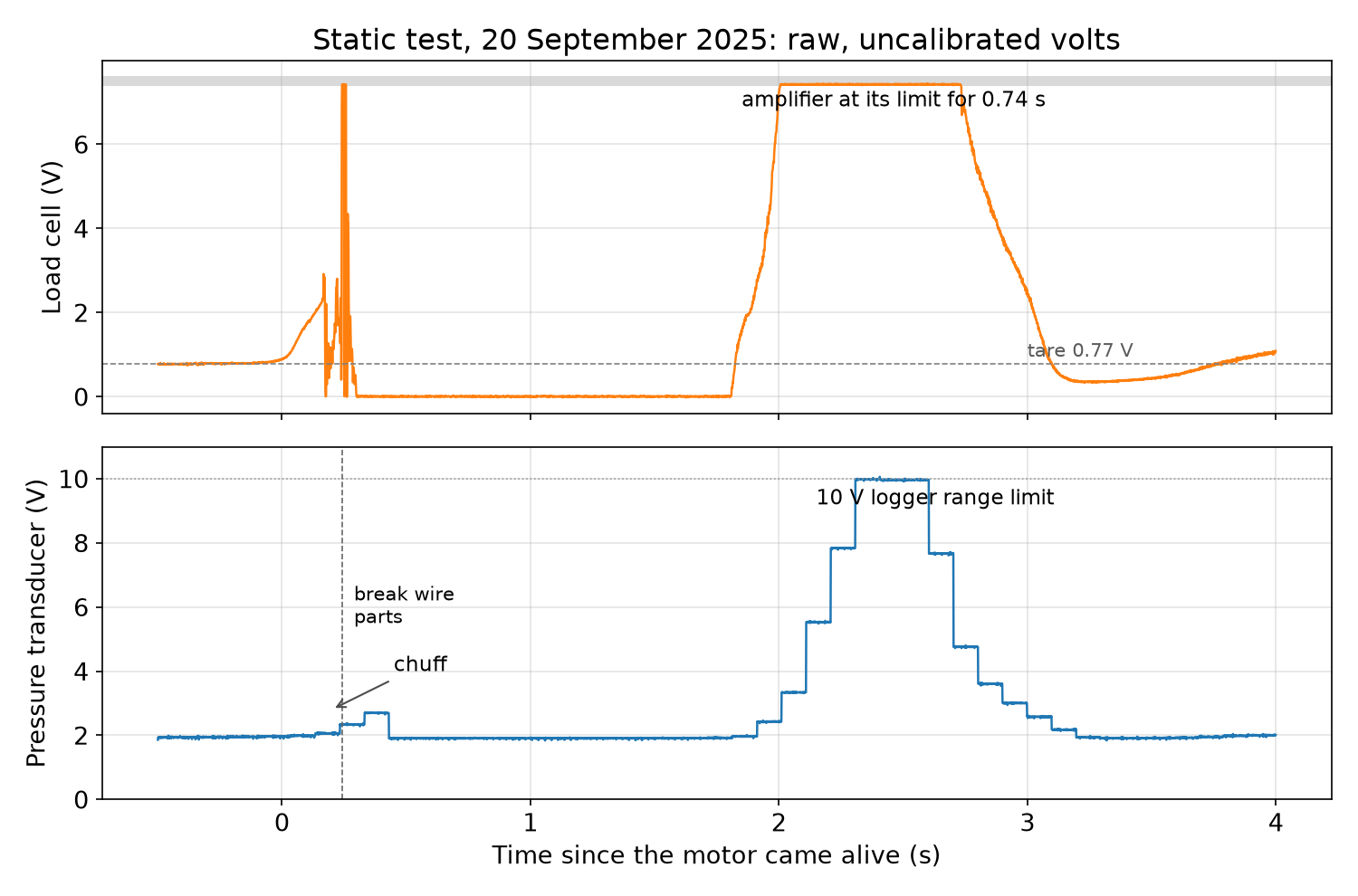
The chart shows the raw voltages, not newtons and bar, and both channels have a problem:
- The thrust channel hit the limit of the load cell amplifier and stayed there for 0.74 s, the whole top of the burn. The rise and the tail-off are recorded; the peak isn’t.
- The pressure channel reached the 10 V upper limit set in the logger configuration at the top of the burn. Its trace also moves in steps of roughly 0.1 s rather than smoothly, so it shows the shape of the pressure curve but not the detail.
Between the chuff and the main burn, the thrust channel dropped to zero, below its tare value, and stayed there. I don’t read anything into that part of the trace.
With the top of the thrust curve cut off, I can’t calculate the total impulse or the peak thrust from this test. What the log does show is the timing: the main burn, from the moment thrust rises above the tare until it falls back, lasted about 1.3 seconds, against 2.1 seconds predicted. With the pressure channel out of range at the same moment, I can’t tell from this data whether the chamber ran at a higher pressure than the design’s 70 bar.
Taking it apart#
Three days after the test I took the motor apart.
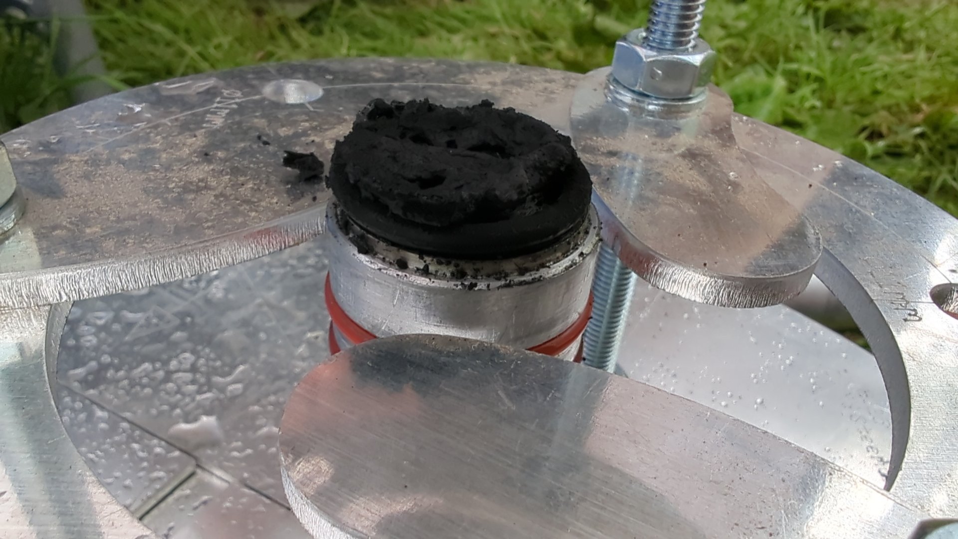
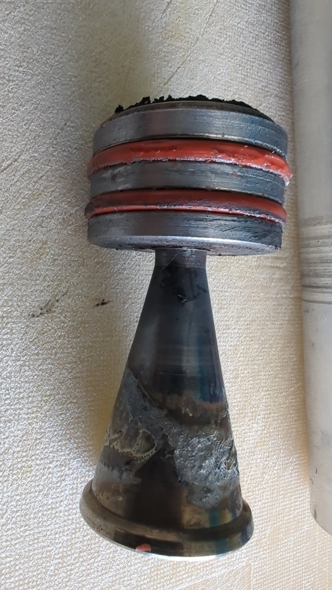
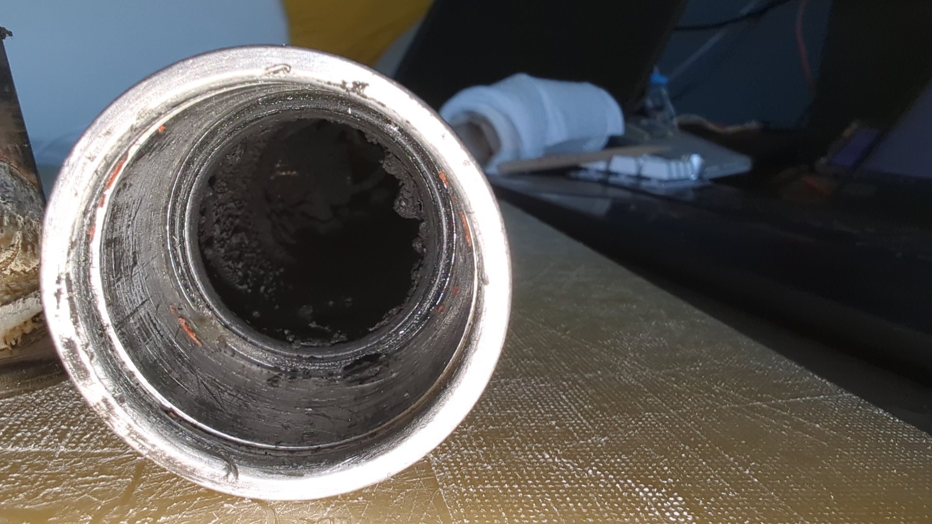
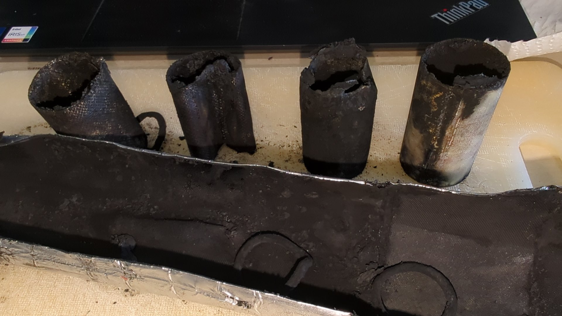
The casing, the closures and the nozzle came through in good shape and can be used again as they are. The liner and the O-rings are the consumables. The liner did its job: it is charred on the inside and partly collapsed, but it kept the heat away from the aluminium.
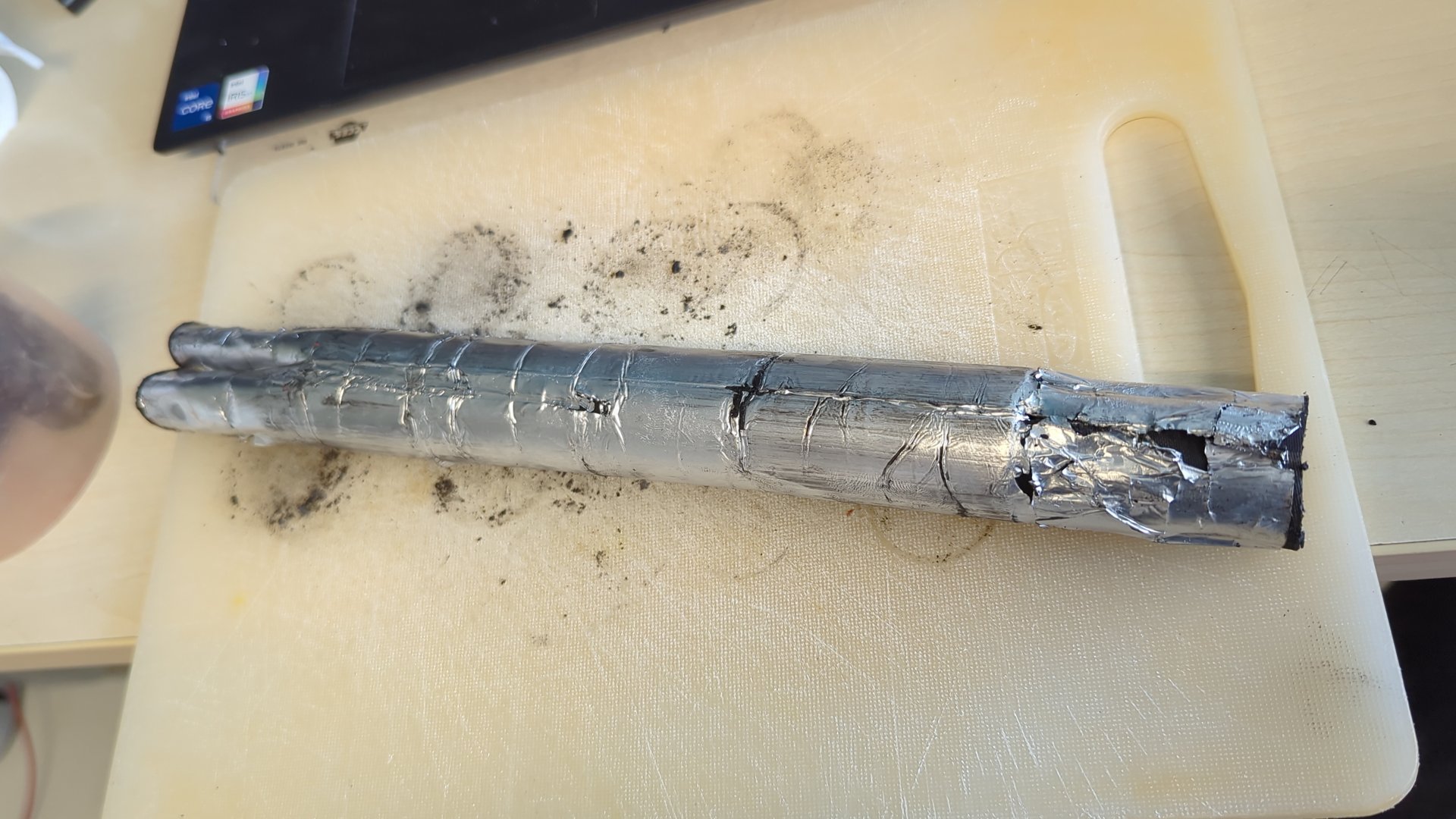
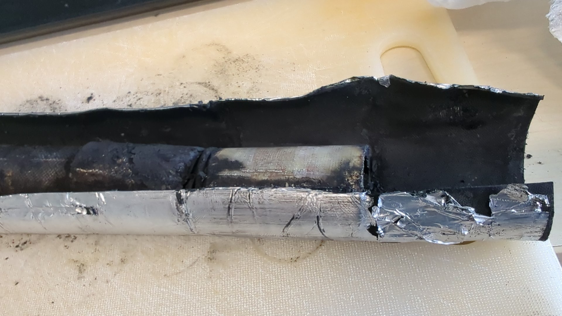
The glass fibre inhibitors came out as empty shells: the propellant inside had burned away completely, and the inhibitors had kept the flame off the outside of the grains, as intended.
What’s next#
The hardware is ready for its next load: a new liner, new O-rings and the grains cast in October 2026. On the measurement side, the load cell amplifier gain needs to come down so the peak fits in the range, the logger’s voltage range has to cover the full output of the pressure transducer, and both channels need a calibration so the next chart is in newtons and bar. Then the I400 gets its first full thrust curve, and a number for its total impulse to compare with the 396 Ns (89 lbf·s) on paper.
Resources#
- Richard Nakka’s Experimental Rocketry Web Site , including the RNX propellant pages and the SRM spreadsheet
- Measuring a Rocket Motor with an NI USB-6009 , the data logger used for the static test
- Ballistic Evaluation Motor test 2 and test 3 , the sugar-propellant tests from 2010 and 2011
- Static Test Controller , the 2010 predecessor of the logger
- A Wireless Rocket Launch Controller on ESP32s