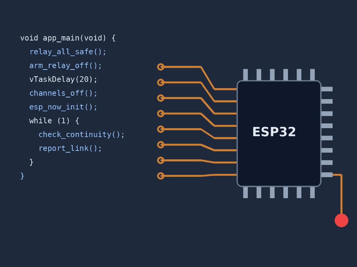

Using AI to write code is no longer news. Plenty of makers have an assistant write a script, a web page or a small app, and it mostly works. What gets less attention is what happens when that code has to leave the screen and drive something physical: a relay, a sensor, a camera shutter, a rocket igniter.
That is where most of my projects live, and over the past year AI has become part of nearly every step of them. Not only the firmware, but also the testing, the choice of parts, the schematics, the analysis of measurements and the reverse engineering of old kit. This post is an overview of what that looks like in practice, with the projects it happened in, the places where it went wrong, and the things I still want to try.
I use Claude Code , an AI agent that runs in a terminal and can read files, run commands and edit code. Most of what follows would work with any agent that can do those three things.
Code is the easy part now#
The gap between software and hardware has always been the physical world. Code can be tested by running it. A circuit can only be tested on the bench, with a meter, and sometimes by letting the smoke out. An AI that can only produce text sits on the software side of that gap.
What changed for me is that an agent with access to a shell is no longer limited to text. It can compile firmware, flash it to a board over USB, read what the board says back and act on it. That turns it from a code generator into something closer to a lab assistant. The rest of this post follows that idea through the stages of a hardware project.
Firmware#
The biggest project where AI wrote the firmware is my ESP32 wireless rocket launch controller : a base unit at the pad and a handheld remote, two ESP32-S3 boards talking over encrypted ESP-NOW. The base switches eight igniter channels through relays, checks igniter continuity, sounds a siren and refuses to arm unless a physical key switch is turned and the arm relay is verified to have closed. The deep dive has the details.
A few things made this work better than I expected:
- Write the spec first. The launch controller has a functional specification that describes every state, message, timeout and test. The AI writes code against that document, and code reviews check the code against it. When something is unclear, the spec gets fixed first.
- Build in phases. Link layer, then the arming logic, then the display, then the field features. Each phase ends with tests on real hardware before the next one starts.
- Give it the datasheet, not its memory. An AI knows a lot about the ESP32, but its memory of a specific pin is a guess. With the datasheet and the board’s pin map in the project folder, it avoids things like strapping pins (on the launch controller, channel 2 moved from GPIO 3 to GPIO 10 for that reason) and input-only GPIOs.
- Safety logic is still logic. Arming sequences, interlocks, watchdogs and link-loss behaviour are state machines, and state machines are something AI handles well, as long as the spec says what “safe” means.
Smaller projects follow the same pattern with less ceremony: controlling a RunCam Thumb camera with an ESP32-C3 , and apps for the Fri3d badge, from my first vibecoded app to Fri3d Friends , a BLE friend finder.
Closing the loop over USB#
This is the part that makes the biggest difference. The board sits on my desk, connected over USB. The AI compiles the firmware, flashes it, opens the serial port, reads the boot log and sends commands. If a test fails, it reads the output, changes the code and runs it again. I don’t copy logs back and forth; it closes the loop itself.
A few practical details make this reliable:
- Stable port names. On Linux,
/dev/ttyACM0and/dev/ttyUSB1change every time a board is replugged. The AI always uses the/dev/serial/by-id/path instead, preferably one based on the USB-to-UART bridge’s serial number rather than the chip’s MAC address, because that one survives a chip swap. - A list of every board. Once, with several ESP32 boards plugged in at the same time, the AI flashed the wrong one. Since then there’s a local file with the USB IDs of every board I’ve ever connected, what each one is and which project it belongs to. Before flashing, the AI looks up the port in that file to make sure it has the right board. The file works as a memory of all the hardware on my desk, past and present.
- Tests it can run itself. A test specification lists each test, its steps and its pass criteria. The AI runs the ones it can and writes a test report.
- Fault injection. Some failures are hard to cause by hand: a lost radio link at the worst moment, a corrupted message, a relay that does not respond. The launch controller has special test builds that inject those faults on purpose, clearly marked so they can never be mistaken for a real build.
- Guided manual tests. Anything I have to press, look at or listen to stays manual. The AI then walks me through it one step at a time and records what I report.
The same loop works for measurements. For the D3000 camera rig (more about that below) I soldered wires to the camera’s shutter switch and measured each line: the half-press line sits at 4.71 V idle and the full-press line at 3.31 V, with short-circuit currents of 0.12 mA and 0.064 mA. From those numbers the AI worked out that a PC817 optocoupler, which saturates at 0.1 to 0.2 V, will pull both lines low reliably, and that the full-press line only works while the half-press line stays closed. Bench logs went the same way: EXIF timestamps of a test burst gave the real frame rate, and a standby test gave the real current draw.
Choosing parts and drawing schematics#
The D3000 project is a rocket liftoff camera: an old Nikon D3000 DSLR that shoots bursts of about 3 frames per second, triggered remotely. A camera node with an ESP32-S3 sits with the camera 5 to 10 m (16 to 33 ft) from the pad, and a small handheld remote controls it. When my own launch controller fires the motor, its base sends an optically isolated trigger signal at T−2 s, so the pictures take themselves.
Most of the design work was done with AI:
- Choosing the approach. The D3000 has no wired remote port. Its infrared remote only fires single frames, and USB tethering isn’t supported. The AI laid out the options, including a servo or linear actuator pressing the shutter button, and we picked a wired release inside the camera.
- Choosing parts, with a reason for each. PC817 optocouplers for the half and full press, a 2S2P pack of 18650 cells, fuses sized so the right one blows first, a TP4056 charger for the remote. The parts list was priced at my local supplier with a link to every product page.
- A power budget. The remote draws about 185 mA from its cell, which gives about 16 hours, enough for a launch day.
- Schematics as code. The schematics are drawn by a Python script that writes SVG, using drawing functions that were first written for the launch controller and then reused. Changing the design means changing the script and regenerating the drawing.
- Spec changes as checked edits. When I decided the remote needed no arming switch (it’s a camera trigger, an accidental press only wastes a few frames), that one decision touched the whole specification. The AI made it in 56 replacements, each checked to match exactly once, and moved the spec from version 0.14 to 0.15.
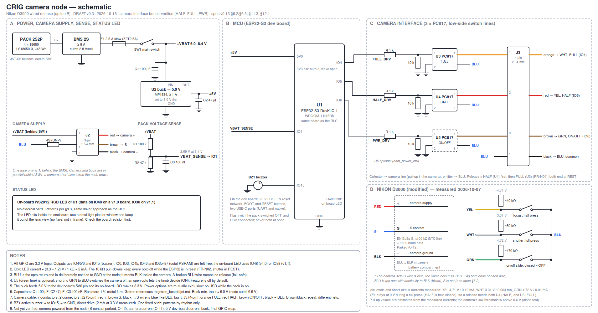
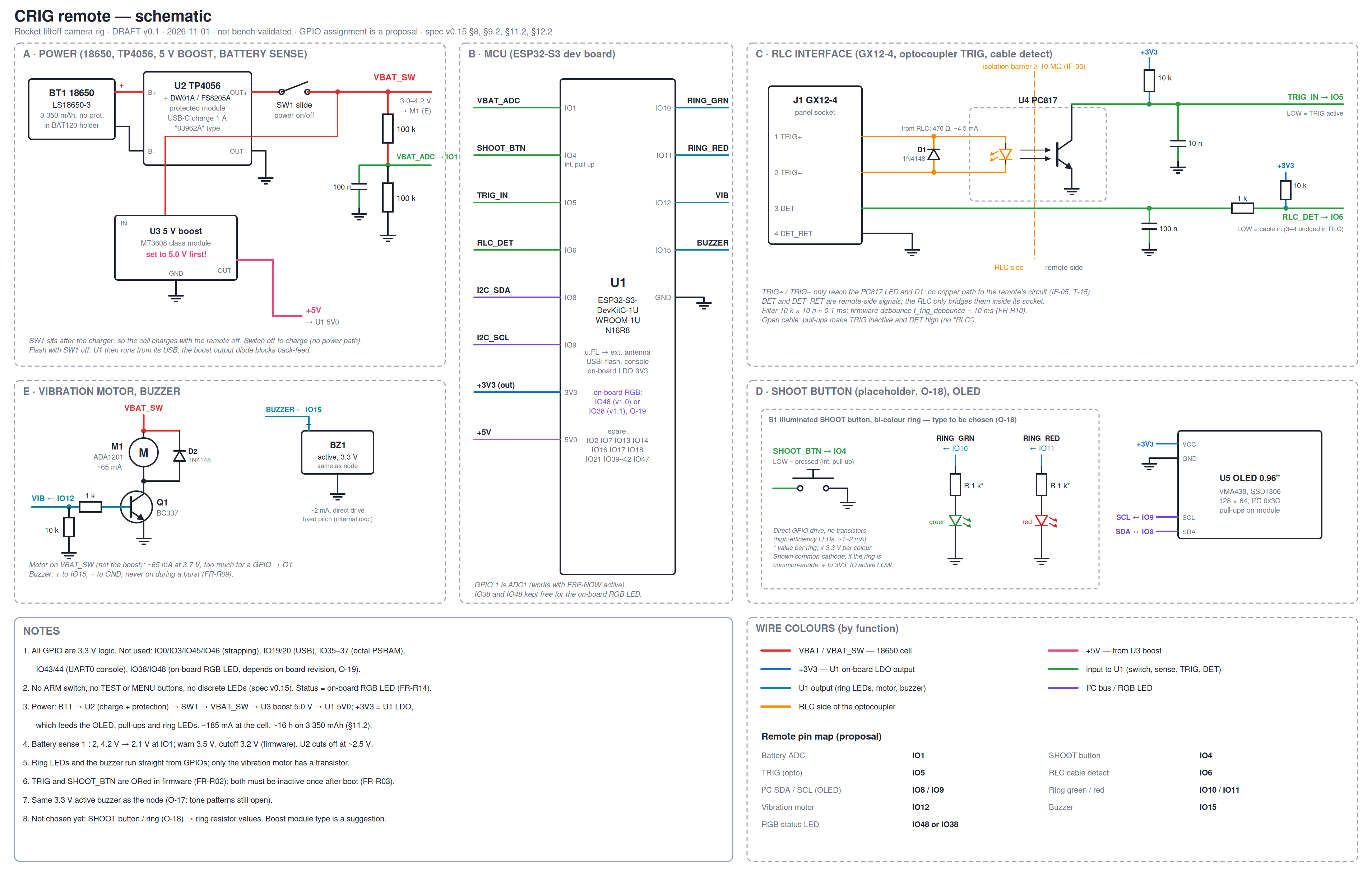
The launch controller got the same treatment afterwards: its base and remote schematics were drawn as built and then compared with the original hand-drawn design, and the differences were written down instead of quietly corrected.
Making sense of measurements#
Rocketry produces a lot of data, and AI is good at questioning it.
The best example is the flight log of my Level 2 certification flight . The altimeter, an Eggtimer Proton, logs both a barometer and an accelerometer. When the AI compared the two, they didn’t agree in time. It turned out the logger is set to 33 samples per second but actually records about 20, while stamping each sample as if it were 1/33 s apart. All times up to nose-over have to be multiplied by 1.67. The audio of the video and a reconstruction of the thrust curve confirmed it. The same fix then corrected my Level 1 log too, and showed that the flight reached 30% less altitude than the simulation, where the old post had said it matched.
Static tests are the other source. My NI USB-6009 logger records thrust and chamber pressure for motors like the I400 . That test had no calibration factors and both channels clipped, and the AI was clear about what that meant: the chart stays in raw volts, and no impulse or peak thrust can be claimed from it.
Talking to existing hardware#
A lot of hardware projects start with something that already exists and doesn’t talk.
Bringing a second-hand Solar-Log 500 online meant finding a device that was invisible on the network, getting an RS485 connection to the inverter right (with a polarity trap), and getting past a firmware problem before it would report anything to Home Assistant. The USB-6009 logger gave an old data acquisition box that was lying around a second life.
The D3000 had one more surprise. I wanted to power the camera from the node’s battery pack through a dummy battery. The camera refused it. The original battery’s centre contact measures about 100 kΩ to minus (102 kΩ when I checked it again today), and a fixed resistor of that value didn’t help. Scope captures showed why: when the battery goes in, the camera and the battery exchange short bursts of data at 9600 baud. The AI wrote an edge detector and a UART decoder for the captures, found a fixed header (0x55 as a sync byte, then 0x25 55 FF) and a payload that changes every time. At that point we stopped on purpose: the camera keeps its own battery, and the project moved on. Knowing when to park something is part of the job.
Calculations and design reviews#
The everyday help is less spectacular: voltage dividers, gate drive for a MOSFET, how much current an igniter draws, how long a battery lasts, whether a fuse will blow before a wire gets hot. These are quick to ask and easy to check.
More valuable is the review. Code reviews of the launch controller are a separate pass, done against the spec, and they find real problems. One example: when an ADC read failed, the function returned 0, and 0 fell inside the range that means “igniter connected”, which is the only state that allows arming. No test had caught it. A review did.
Where it falls short#
AI is good at logic and poor at physics it can’t observe. Every serious problem in my projects came from that gap.
The ESP32 that died on the first fire pulse. In April 2026 the launch controller fired a real igniter on the bench for the first time, and the base unit’s ESP32-S3 died. The firmware switched off the channel relays before the arm relay. With 12 V still on the fire bus, the channel relay contacts opened under about 6 A, the arc coupled the battery voltage into the continuity sense inputs, and those had no clamping. The code did exactly what it was written to do; the problem only existed in the physics. The fix was in both places: the arm relay now switches off first, then 20 ms later the channel relays, and the sense inputs got Schottky clamp diodes.
The sense circuit that lied. The remote reported a battery voltage of 5.74 V, and the pack was suspected of being over-discharged. A multimeter showed the pack was fine at about 7.6 V. A 3.3 V zener diode on the ADC input was dragging the reading down. The AI believed the sensor, because the sensor was all it had.
The spec that was wrong. In one test the display showed different text from what the functional spec expected. The code was right; the spec had the wrong expected text. AI follows a document faithfully, including its mistakes.
Facts only the board knows. The rotary encoder on the remote turned the wrong way. The two LED strips were wired from opposite ends, so one unit needs its channel order reversed. The arm relay LED lit up when the key was turned to SAFE, which turned out to be indicator wiring. None of this can be deduced from the code; it’s a property of one particular board, and someone has to look at it.
And one rule doesn’t change: anything that can move, heat up or fire stays under the control of a human. The AI can write and test the arming logic, but I’m the one holding the key.
What I want to try next#
The list of things I haven’t tried yet is longer than the list above. Some of these close the gaps from the previous section; others are just interesting.
Giving the AI eyes and ears on the bench#
- A webcam on the board, so the AI can check a display, an LED strip or an indicator itself. Three of the four “facts only the board knows” above would have been caught that way.
- A microphone, to confirm siren and buzzer patterns by listening instead of asking me.
- A logic analyser under its control, with
sigrok-cli, so it can capture and decode I²C, SPI or UART traffic without me holding the probes. - Instruments it can drive. Scopes, bench supplies and electronic loads that speak SCPI, for unattended measurements like battery discharge curves and current profiles.
- Power control and hardware fault injection. USB hubs with switchable ports or a programmable supply, so it can power-cycle a board or sag the voltage to test brownout behaviour.
- JTAG debugging. The ESP32-S3 has a built-in USB JTAG interface; the AI could drive OpenOCD and gdb, and decode core dumps after a crash.
- Power profiling, measuring deep sleep and runtime with a current profiler instead of calculating them.
Design#
- Circuit simulation. Running the critical parts through SPICE before building them: relay switching transients, clamp diodes on inputs, debounce networks, that zener on the voltage divider. A transient simulation might well have warned about the dead ESP32.
- From drawings to a real PCB. The schematics are SVG drawings today. Tools like SKiDL or KiCad’s scripting could turn the same Python into a netlist, a layout, a design-rule check and Gerber files.
- Enclosures and mechanics, with OpenSCAD or CadQuery, sized from the board and connector dimensions and checked for fit before printing.
- A hazard analysis for the launch controller: a structured table of what can fail, what happens and how it’s caught.
- BOM and supply checks: prices across suppliers, alternatives for parts that are out of stock or end-of-life, and footprints checked against the parts actually bought.
- Regulatory checks: radio band and duty-cycle rules, CE basics, shipping lithium batteries.
AI inside the hardware#
- TinyML on the ESP32-S3. Small models running on the chip itself, for example to spot anomalies in static-test thrust data, or to detect a liftoff from vibration or sound and trigger the camera.
- An MCP server for the bench. I already use MCP servers that give the AI access to Home Assistant and to the Fri3d badge documentation. One for the bench (serial ports, power, instruments, the webcam) would turn everything in this list into tools the AI can call directly, as naturally as it reads a file.
Smaller ones#
- Reading photos of boards: identifying parts from their markings, checking solder joints, comparing a photo of the wiring with the schematic.
- Datasheets in other languages, like the Chinese datasheets that come with cheap modules and sensors.
- Teaching material: explaining a circuit at the reader’s level and generating exercises for someone learning electronics.
Getting started#
If you want to try this yourself, the setup is small:
- a development board, such as any ESP32 dev kit, and a USB cable;
- an AI agent that can run commands on your machine;
- the datasheets and the board’s pinout in the project folder;
- a short written description of what the thing should do.
A good first exercise: have the AI make an LED blink, then have it check over the serial port that the firmware reports what it should, then add a sensor and let it test the readings. Once the AI can flash, read and fix on its own, the rest of this post follows from there. It works for one maker at a desk, and just as well for a small team that never had an embedded developer.
Resources#
- ESP32 wireless rocket launch controller and the deep dive
- Controlling a RunCam Thumb camera with an ESP32-C3
- Bringing a second-hand Solar-Log 500 online
- Measuring a rocket motor with an NI USB-6009
- PML Intruder Level 2 certification flight and Level 1
- The I400 rocket motor
- Fri3d badge: vibecoding my first app , programming the Fri3d badge with Claude Code and Fri3d Friends
- My Claude Code setup
- Claude Code