Running the Fri3d Camp 2024 Badge on ESPHome and Home Assistant
The Fri3d Camp 2024 badge is an ESP32-S3, which makes it a first-class target for ESPHome — and therefore a native citizen of Home Assistant. This post documents a complete ESPHome configuration for the badge: which component drives each piece of hardware, the non-obvious choices that were required, and the entities that show up in Home Assistant once it is flashed. It is a companion to my earlier post on programming the badge with Claude Code ; that one covers the stock firmware and writing MicroPython apps, this one covers replacing the firmware with ESPHome.
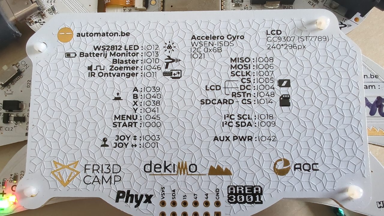
The hardware#
Under the shell the badge is an ESP32-S3-WROOM-1, N16R8V: 16 MB flash, 8 MB
OPI PSRAM, dual-core Xtensa LX7 at 240 MHz, Wi-Fi + BLE. It connects over USB-C
through the chip’s native USB-Serial/JTAG peripheral, so on Linux it appears as
/dev/ttyACM* (CDC, not ttyUSB* — there is no UART bridge chip). The peripherals
relevant to ESPHome:
| Subsystem | Part | GPIO |
|---|---|---|
| Display | GC9307 (ST7789-compatible) IPS, 296×240, BGR | SPI: MOSI 6, SCLK 7, MISO 8, CS 5, DC 4, RST 48 |
| IMU | Würth WSEN-ISDS (accel + gyro), I²C 0x6B | SDA 9, SCL 18, INT 21 |
| LEDs | 5× WS2812 | 12 |
| Buttons | A/B/X/Y/MENU/START | 39/40/38/41/45/0 |
| Joystick | 2-axis analog | X 1, Y 3 |
| Battery | LiPo monitor (divider) | 13 |
| Buzzer | passive | 46 |
| IR receiver | 11 |
ESPHome configuration#
The full config lives in
esphome/fri3d-badge.yaml
in the project repo. The board is declared as esp32-s3-devkitc-1 with the Arduino
framework, and the logger is routed to USB_SERIAL_JTAG so boot output appears on
the same /dev/ttyACM0 port. Most peripherals map to standard ESPHome components,
but four of them needed specific handling.
IMU — the unified lsm6ds motion driver#
The WSEN-ISDS is Würth’s rebrand of ST LSM6DS3 silicon: it answers WHO_AM_I
0x6A at I²C address 0x6B. ESPHome 2026 has no dedicated lsm6ds3 component;
instead the LSM6DS family is exposed through the unified motion platform. The
device is declared under motion:, and the axis sensors under sensor: with
platform: motion:
motion:
  - platform: lsm6ds
    id: imu
    address: 0x6B
    accelerometer_range: "4G"
    gyroscope_range: "500DPS"

sensor:
  - platform: motion
    motion_id: imu
    type: acceleration_x
    name: "Accel X"
  # ... acceleration_y/z, gyroscope_x/y/z
NeoPixels — esp32_rmt_led_strip, not neopixelbus#
The five WS2812 LEDs on GPIO12 are configured with esp32_rmt_led_strip. The older
neopixelbus platform cannot be used here: it pulls in ESP-IDF’s legacy RMT
driver, which conflicts with the new RMT driver that remote_receiver (the IR
receiver) uses — the two define rmt_channel_t differently, and the build fails.
The new driver avoids the clash:
light:
  - platform: esp32_rmt_led_strip
    id: badge_leds
    pin: 12
    num_leds: 5
    rgb_order: GRB
    chipset: WS2812
    use_psram: false
    name: "Badge LEDs"
    effects:
      - addressable_rainbow:
      - pulse:
      - strobe:
Display — GC9307 via mipi_spi with a custom model#
The display was the only subsystem that needed real reverse-engineering. The
GC9307 is GalaxyCore’s ST7789-class controller, but its native framebuffer is
296×240 addressed directly — not the 240×320 geometry of a stock ST7789V.
ESPHome’s st7789v component is deprecated and model-fixed, and the ST7789V
entry in its successor mipi_spi carries a 240×320 native size, so a 296-wide
panel fails validation with “invalid offsets”.
The working configuration uses the mipi_spi CUSTOM model, which has no fixed
native geometry and accepts a full init_sequence. The orientation, dimensions,
SPI speed and init bytes are taken verbatim from the badge’s own Retro-Go firmware
(components/retro-go/targets/fri3d-2024/config.h in the Fri3dCamp repo), which is
the authoritative source for this panel:
display:
  - platform: mipi_spi
    model: CUSTOM
    dimensions:
      width: 296
      height: 240
    color_order: BGR
    invert_colors: false
    cs_pin: 5
    dc_pin: 4
    reset_pin: 48
    data_rate: 40MHz
    transform:                # → MADCTL 0x28 (MV | BGR)
      swap_xy: true
      mirror_x: false
      mirror_y: false
    init_sequence:
      - [0xCF, 0x00, 0xC3, 0x30]
      - [0xED, 0x64, 0x03, 0x12, 0x81]
      - [0xE8, 0x85, 0x00, 0x78]
      - [0xCB, 0x39, 0x2C, 0x00, 0x34, 0x02]
      - [0xF7, 0x20]
      - [0xEA, 0x00, 0x00]
      - [0xC0, 0x1B]
      - [0xC1, 0x12]
      - [0xC5, 0x32, 0x3C]
      - [0xC7, 0x91]
      - [0xB1, 0x00, 0x10]
      - [0xB6, 0x0A, 0xA2]
      - [0xF6, 0x01, 0x30]
      - [0xF2, 0x00]
      - [0xE0, 0xD0, 0x00, 0x05, 0x0E, 0x15, 0x0D, 0x37, 0x43, 0x47, 0x09, 0x15, 0x12, 0x16, 0x19]
      - [0xE1, 0xD0, 0x00, 0x05, 0x0D, 0x0C, 0x06, 0x2D, 0x44, 0x40, 0x0E, 0x1C, 0x18, 0x16, 0x19]
The transform block is what produces the correct MADCTL 0x28 (MV | BGR):
swap_xy sets the MV bit, the colour order comes from color_order: BGR. ESPHome
automatically inserts the SLPOUT, COLMOD, MADCTL, INVOFF and DISPON commands around
the supplied init sequence, so those are omitted above. The SPI clock is 40 MHz,
matching Retro-Go; running it at the 80 MHz the MicroPython firmware uses caused long
stalls on the first framebuffer transfer.
Battery — ADC2 on GPIO13#
Battery voltage is read on GPIO13, which on the ESP32-S3 is ADC2 channel 2
(the silkscreen’s “ADC1_CH12” label is incorrect — that mapping belongs to a
different ESP32 variant). The Retro-Go configuration gives the divider and the
state-of-charge range: a 2:1 divider, with 3.15 V mapped to 0 % and 4.15 V to
100 %. It is implemented as an adc sensor plus two template sensors for voltage
and percentage. On the original ESP32, ADC2 is unusable while Wi-Fi is active; on
the ESP32-S3 here it reads correctly with Wi-Fi connected.
sensor:
  - platform: adc
    id: batt_raw
    pin: 13
    attenuation: 12db
  - platform: template
    name: "Battery voltage"
    lambda: return id(batt_raw).state * 2.0;
  - platform: template
    name: "Battery level"
    unit_of_measurement: "%"
    device_class: battery
    lambda: |-
      float v = id(batt_raw).state * 2.0;
      if (isnan(v)) return {};
      float pct = (v - 3.15) / (4.15 - 3.15) * 100.0;
      if (pct < 0.0) pct = 0.0;
      if (pct > 100.0) pct = 100.0;
return pct;Flashing#
The ESPHome firmware is a full replacement: it overwrites the bootloader, the
partition table and the application. With Wi-Fi credentials and an API key placed
in a gitignored secrets.yaml, it compiles and flashes over USB:
esphome compile esphome/fri3d-badge.yaml
esphome upload  esphome/fri3d-badge.yaml --device /dev/ttyACM0
After it boots and joins the network it advertises itself over mDNS as
fri3d-badge.local. In Home Assistant, Settings → Devices & Services → ESPHome
discovers it; adding the node requires the Noise encryption key from secrets.yaml.
The camp firmware is fully restorable. A verified 16 MB full-flash dump of the stock image is kept in the repo, and writing it back returns the badge to its original state in one command:
esptool --port /dev/ttyACM0 write_flash 0x0 \
  backups/fri3d-badge-2024_full-flash_2026-07-02.bin
What appears in Home Assistant#
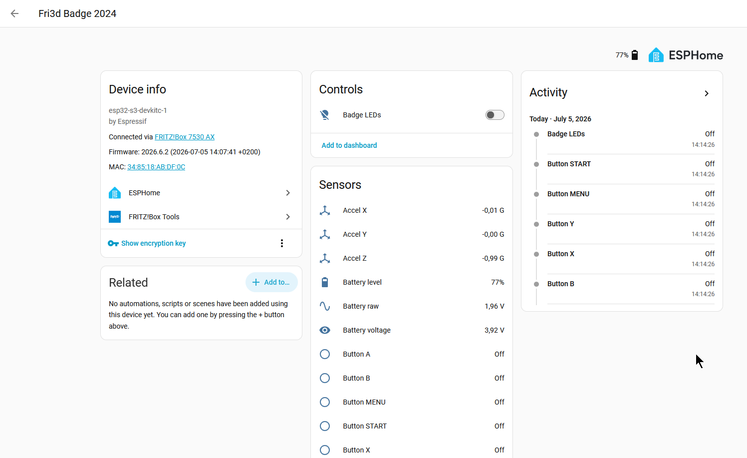
Once adopted, the badge exposes its full I/O to Home Assistant. Measured values on a badge lying flat on the desk:
| Entity | Reading |
|---|---|
| Accel X / Y / Z | 0.00 / 0.00 / −0.98 g (gravity down the Z axis) |
| Gyroscope X / Y / Z | ~0 °/s |
| IMU temperature | 22.5 °C |
| Joystick X / Y | 1.31 / 1.74 V |
| Battery voltage / level | 3.92 V / 77 % |
| Buttons A B X Y MENU START | six binary sensors |
| Badge LEDs | one addressable light (rainbow / pulse / strobe) |
The accelerometer reading is the useful sanity check: with the badge lying flat, gravity reads approximately −1 g on the Z axis and near zero on X and Y.
Two operational notes#
- The badge joins a FRITZ!Box mesh, and the first connection attempt to the strongest mesh node fails authentication every boot before succeeding on the immediate retry. It is a PMF negotiation quirk that costs about five seconds and self-corrects.
- On this ESP32-S3’s USB-Serial/JTAG, serial log output stops once Wi-Fi connects.
The full boot dump (all component configuration and the Wi-Fi handshake) prints to
/dev/ttyACM0, but steady-state sensor values do not — read those from Home Assistant instead.
Resources#
- Project repo (config + docs)
—
esphome/fri3d-badge.yaml - ESPHome documentation
- ESPHome
mipi_spidisplay component Fri3dCamp/badge_retro-go— source of the display init/MADCTL/dimensions (targets/fri3d-2024/config.h)Fri3dCamp/badge_2024_arduino— authoritative pin map- Programming the Fri3d Camp 2024 Badge with Claude Code — companion post on the stock firmware and MicroPython apps