A Wireless Rocket Launch Controller on ESP32s
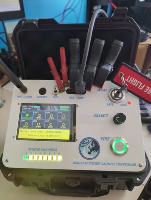
The last time I built launch electronics for a rocket, it was 2008 and the brain of the thing was a PIC16F88 running a four-channel flight timer. Eighteen years later I found myself building something rather bigger: a two-unit, wireless launch controller for VRO, Vlaamse Raket Organisatie , built on a pair of ESP32-S3s, that sits between the LCO’s thumb and a pyrotechnic igniter. Over a radio link.
That last part usually raises an eyebrow. Wireless and pyrotechnics sound like they belong in different rooms. But somewhere along this build I arrived at a counterintuitive position: done properly, a wireless link can be safer than a spool of copper, because you can’t trust a radio the way you lazily trust a wire. The wire invites you to assume safety. The radio forces you to design it.
The problem with wires#
A classical launch controller is a box of relays at the pad and a firing box 200 metres away, joined by a long cable. That cable is expensive, heavy, and forever tangled. Worse, at 200 m the resistance of all that copper eats into the current available at the igniter, the very current the whole system exists to deliver. And the cable itself becomes a safety discussion: every metre of buried or dragged wire is a metre that can be nicked, shorted, or tripped over.
The obvious modern answer is two units with a radio between them: a base unit that lives at the pad, wired to up to eight igniter channels, and a handheld remote unit the Launch Control Officer (LCO) carries at a safe distance. Both are built on the ESP32-S3-DevKitC-1 and talk over Espressif’s ESP-NOW protocol, measured at 430 m at −91 dBm with external antennas, which comfortably covers our firing distances.
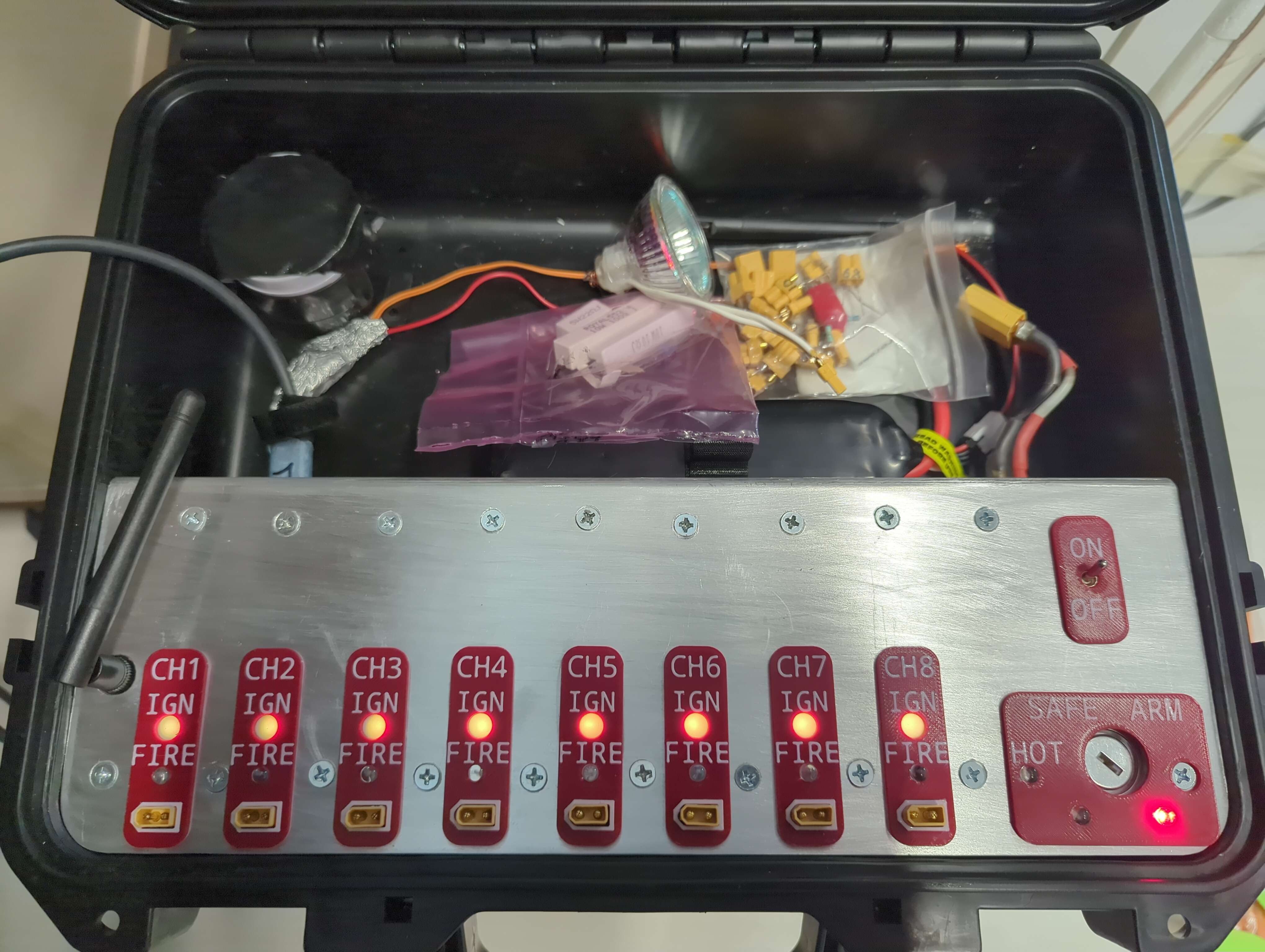
The base unit, as it lives at the pad: eight igniter channels, the arm key, and the siren, all in one case.
The catch is what happens when the thing between your finger and an igniter is software and a radio instead of copper. That’s the part that had to be engineered, and it’s the part that made the project worth doing.
What a launch looks like#
Before the safety story, here’s the machine itself. A complete launch sequence, as the operator experiences it:
- Both units power up and link automatically.
- The LCO selects a channel (1–8) with a rotary encoder on the remote.
- Walking to the pad, the LCO turns the base unit’s physical arm key to ARM, then walks back.
- At the firing point, the LCO turns the remote’s own physical arm key to ARMED.
- A long press (500 ms) on the encoder sends the arm command.
- The base checks a long list of guard conditions, energises its arm relay, and the pad siren starts. And stays on.
- The LCO presses and holds the fire button. A 5-second countdown runs.
- The channel relay closes for exactly one second of igniter current.
- Letting go of the button at any point cuts power immediately. The fire button is a dead-man switch, not a latch.
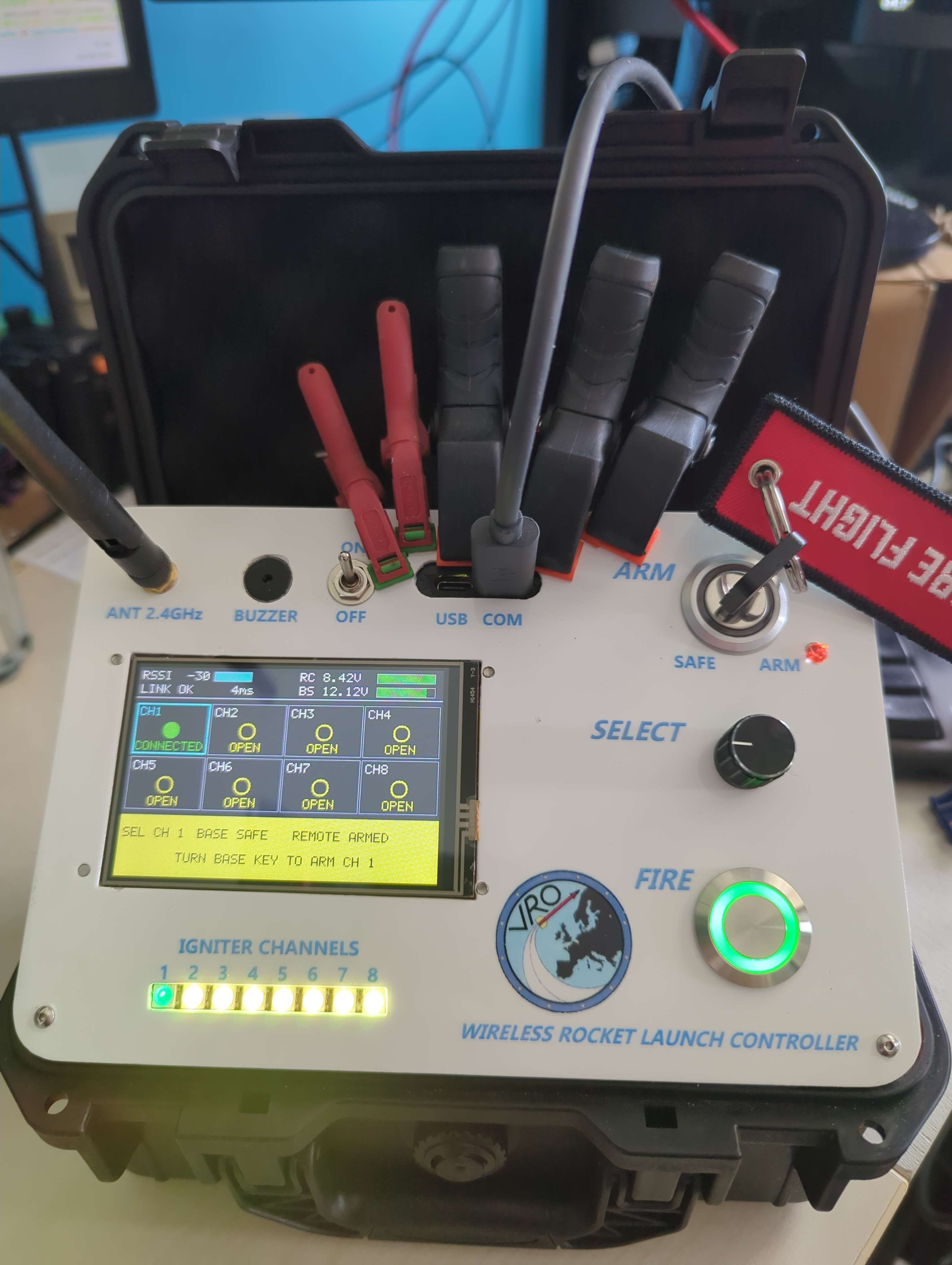
The finished handheld remote the LCO carries at the firing point.
The remote carries a 480×320 ILI9488 colour display. The main screen shows all eight channels as a grid with live continuity, every igniter is sensed with about a milliamp, far too little to heat one, and reported as connected, marginal or open. Each state has its own shape as well as its own colour, so the grid stays readable for colour-blind operators and in poor light.
The boot screen picked up a treat late in the project: while the remote waits for the base to answer, it plays actual video, the two Falcon Heavy side boosters landing at LZ-1, cut from NASA’s public-domain footage, in a 480×160 band across the top of the panel, with the title drawn over it. Not the whole panel, and that’s physics rather than modesty: the ILI9488 is 18-bit-only over SPI, so a full frame costs 184 ms of wire time against a 100 ms frame budget. Full-screen video isn’t slow on this hardware, it’s arithmetically impossible. The band is what fits.

The boot screen as it ships: real footage in the top band, the title drawn over it, and the connection progress underneath.
Across the bottom of every screen runs a coloured status band that reports
the state of the fire path in plain words: green SAFE, orange READY TO ARM,
red ARM RELAY LIVE, and so on. The idea is that the band is legible from
across a launch site without reading anything. And critically, when the system
doesn’t know its own state (link down, stale data), the band is grey, never
green. Green is a positive claim that the pad is safe to approach. It must
never be produced by absence of information.
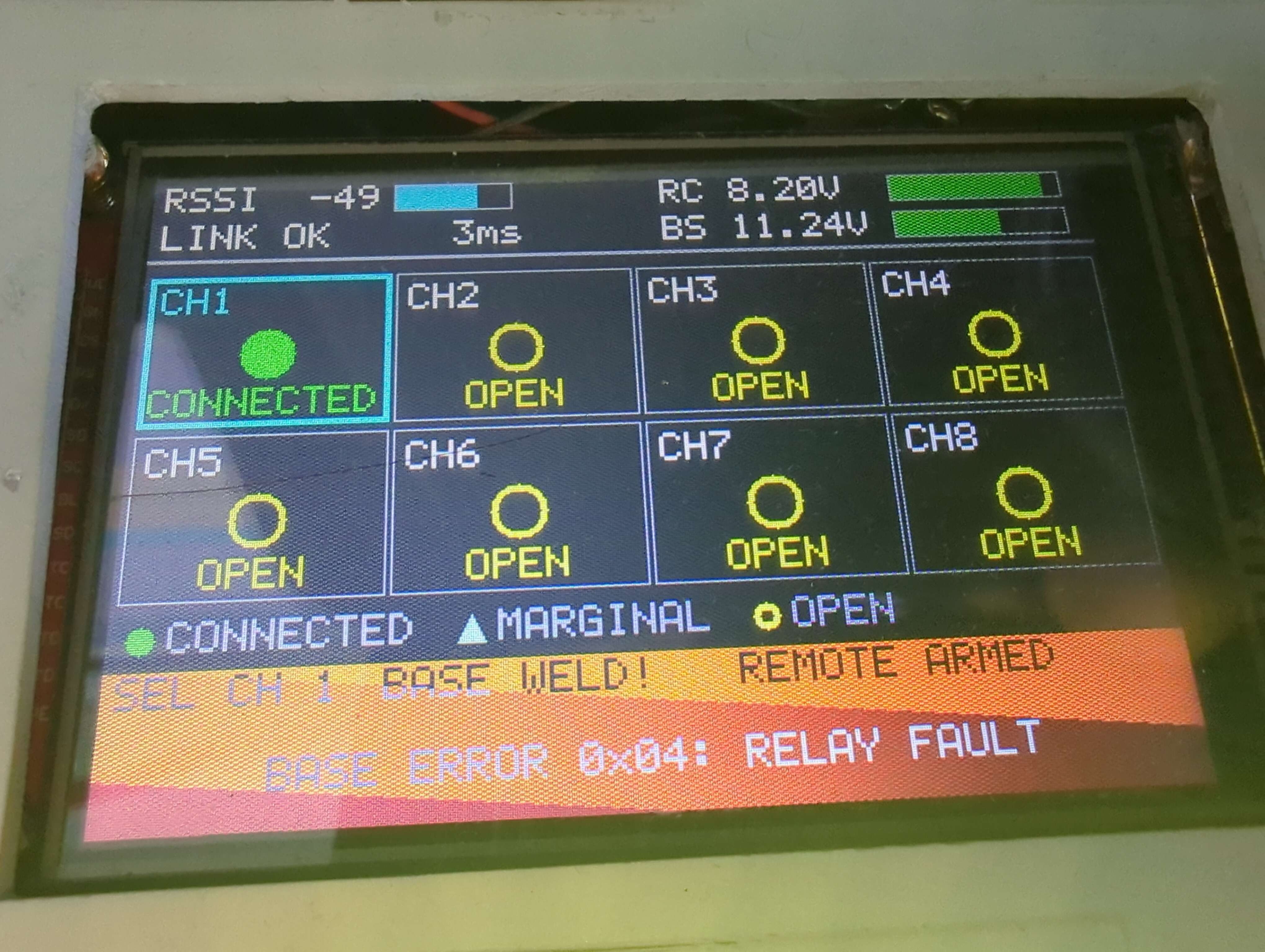
A welded-relay fault as the operator sees it: the status band names the state in words, not just colour.
Both units also carry an 8-pixel NeoPixel strip, one pixel per channel, so the base panel itself shows continuity through the little lenses above each socket, and the base siren sounds continuously from the moment the arm relay closes. You should be able to stand at a pad and know it’s live with your eyes closed.
The safety case#
The whole design answers one sentence: no single hardware or software fault may be able to cause ignition. Everything else follows from it.
Two breaks in the fire path. Current can only reach an igniter through two independent relays in series, the arm relay and the selected channel relay. Both must close for anything to happen. A welded contact in either one, alone, ignites nothing.
The arm key is not where you think it is. The obvious design puts the key switch in series with the igniter as a third break. I didn’t. The key sits in the arm relay’s coil drive path, in series with a firmware-driven MOSFET. That combination is a hardware AND gate: with the key in SAFE there is no coil current available at all, so no software fault, none, not a stuck GPIO, not a hacked radio command, can close the first break. It’s a stronger position than another contact in the fire path, and I later verified it electrically, right at the arm-sense node, with a purpose-built test rig.
Everything fails toward safe. The relays are the type whose coils must be energised to close, with gate pulldowns that hold them off while the ESP32 is still booting. Inputs are active-low, so a broken wire reads as “safe”. The status lamps that say the pad is hot are passive LED circuits that work even if the microcontroller is completely dead. And if the firmware concludes something is genuinely wrong, it doesn’t attempt to self-heal: it latches an ERROR state that only a physical power cycle clears.
The operator can’t be forgotten. The fire button is a dead-man switch, release cuts current, always. Firmware re-checks continuity and battery state before and during arming, auto-disarms after 10 seconds of armed inactivity, listens for a tell-tale that the arm relay has welded shut, and every refusal the system can make produces both a sound and a message on the display. A refusal that only beeps is indistinguishable from a button that didn’t register, and the natural human response to apparent non-response is to press again, which is exactly the wrong instinct at a launch pad.
And the link itself. ESP-NOW with AES-128-CCM encryption, an application-layer integrity check on top of it, and replay protection via sequence numbers and a per-session token. Both units must run byte-identical firmware versions or they refuse to link at all. During firing the remote keeps repeating its intent, so a dropped packet means “stop”, never “keep going”.
None of this is exotic. Relays, keys, pulldowns. It’s the kind of electronics a maker has in a drawer. The value is in assembling them so every failure has somewhere safe to land.
The hardware#
Under the panels, both units are refreshingly ordinary.
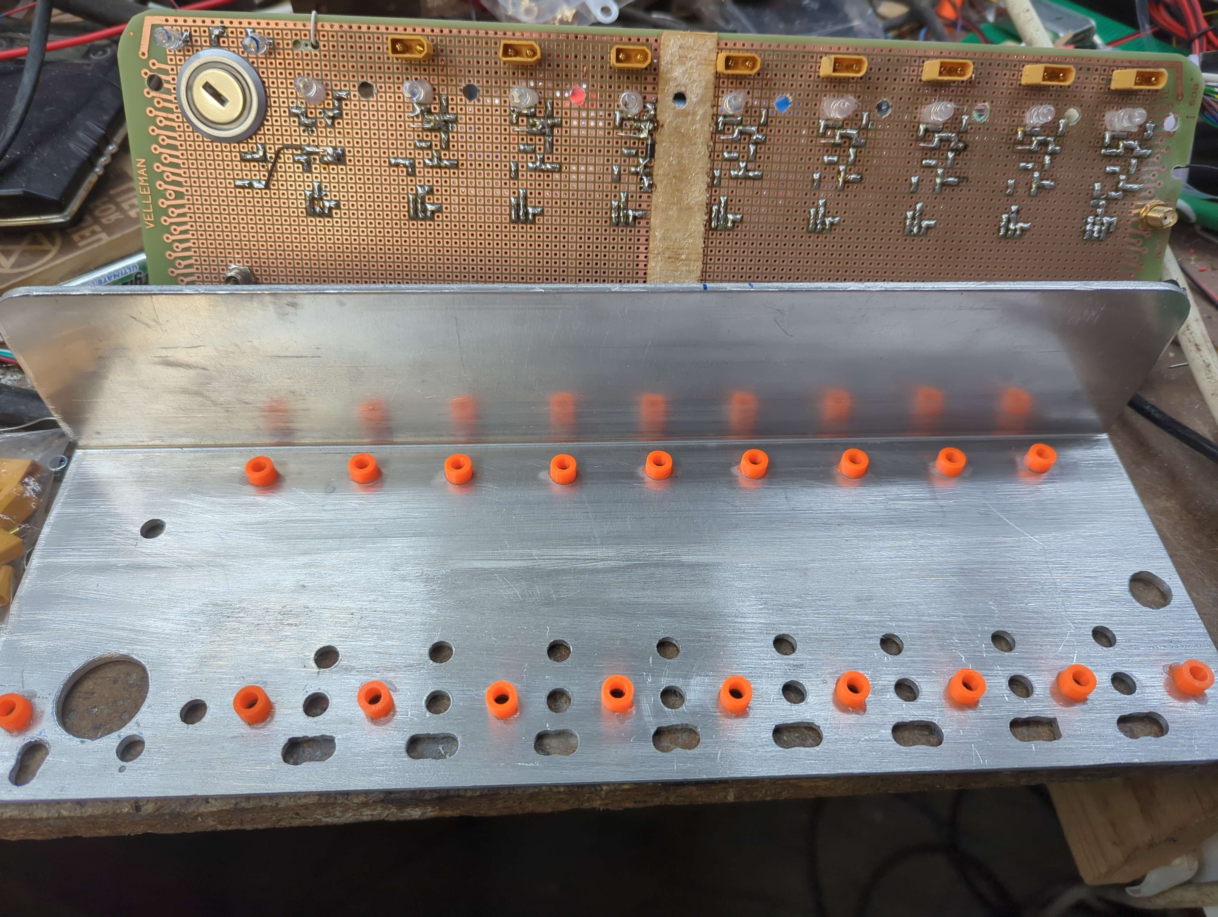
The base under construction: the eight-channel relay board and the ESP32-S3 devkit driving it.
The base unit is an eight-channel relay board (with RC snubbers and clamping diodes added per channel, relays switching inductive loads are rude to the electronics around them), the arm relay, a 3S 5000 mAh LiPo, the siren driver, and the ESP32-S3. The remote unit runs off a 2S 2200 mAh pack and carries the encoder, arm key, fire button, buzzer, display and its own status strip.
Both units have full drawn schematics, generated from the specification and, for the base, reconciled against the built unit, in the deep-dive post .
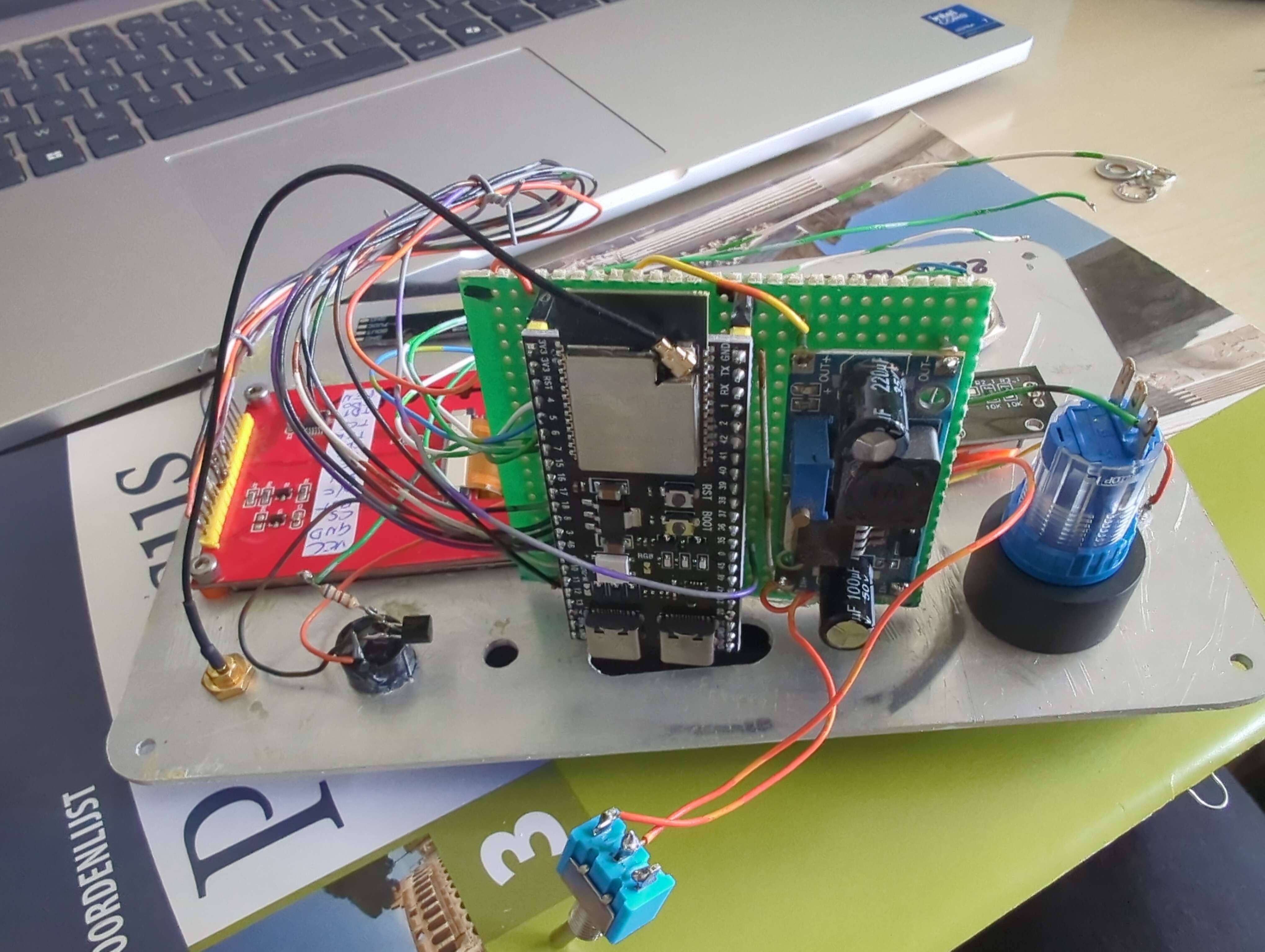
Inside the remote: the same devkit, the display, and a lot of hand-wiring.
It all started far more humbly, on veroboard:
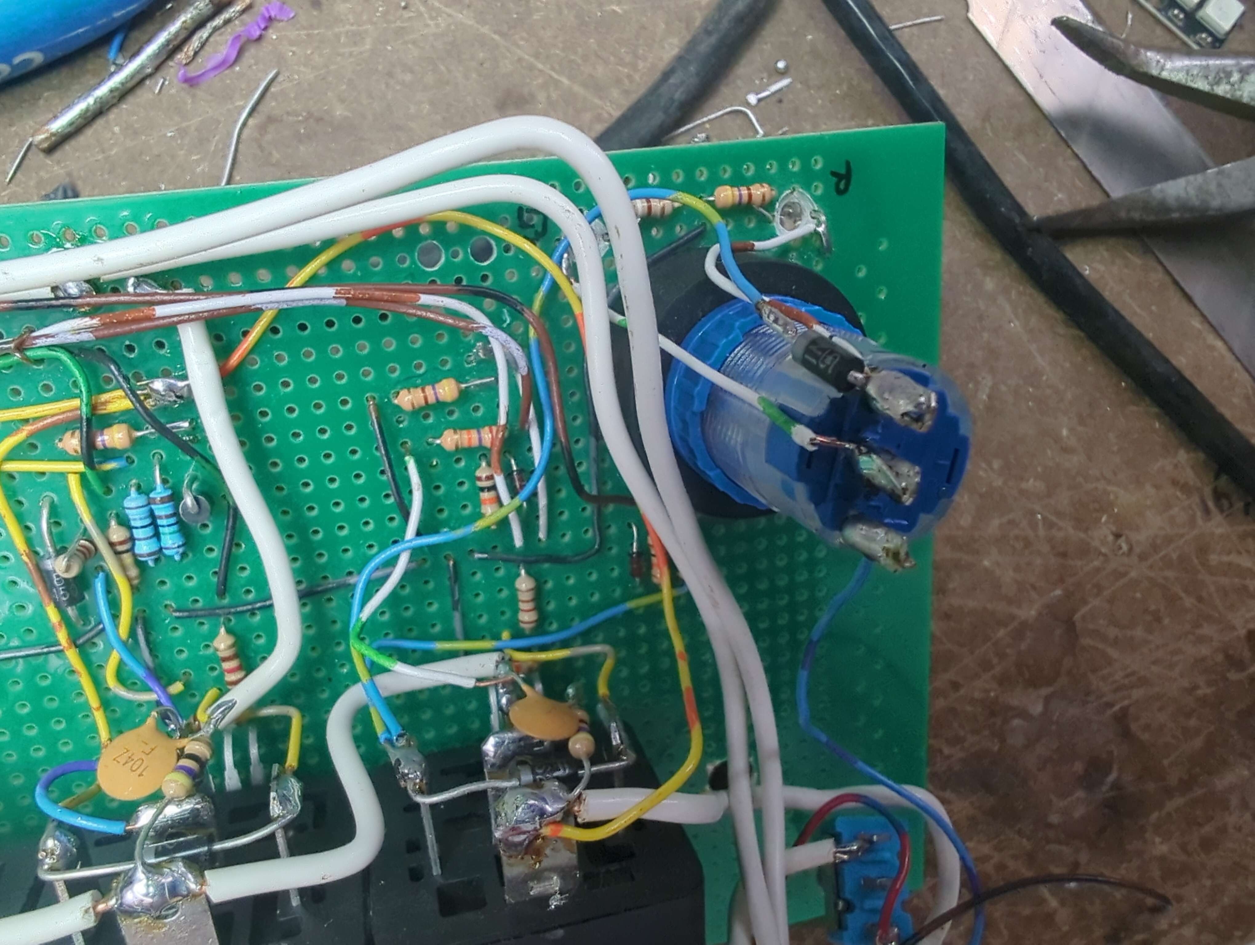
The first prototype, built up on veroboard.
For range testing I took the pair outdoors, put the base on the ground with its antenna up, and walked the remote down a field. The first run measured 200 m at −93 dBm; a second test in the same geometry more than doubled it, 430 m and still −91 dBm, with 5–8 dB of margin left before the link would drop. (RSSI isn’t calibrated, so don’t read too much into one number being “stronger” at the greater distance.) Theory says near the ground propagation degrades with roughly the fourth power of distance, my first test matched that model, and its extrapolation turned out to be pessimistic by some 15 dB. Either way, the practical lesson holds: a metre of antenna height buys you more than any amount of transmit power.
One hardware habit worth copying: I never once referred to the boards by
/dev/ttyACM0. Every serial port on my bench is addressed through its stable
/dev/serial/by-id/ path, because those ACM numbers reorder on every replug,
and flashing firmware at the wrong board is the kind of mistake that costs an
afternoon.
Panel craft#
The electronics were half the build. The other half was turning two aluminium boxes into something that looks like an instrument. And a couple of techniques from the workshop carried far more weight than they had any right to.
The base panel: quick and dirty, then printed over#
The base’s front panel is 3 mm aluminium, and its openings were made like this: rough-drilled and filed to the line. No CNC, no nibbler, no laser-cut file, just a drill, a cheap set of files and a certain amount of optimism. The result was structurally fine and cosmetically a mess: ragged edges, slightly wobbly cut-outs, tool marks everywhere.
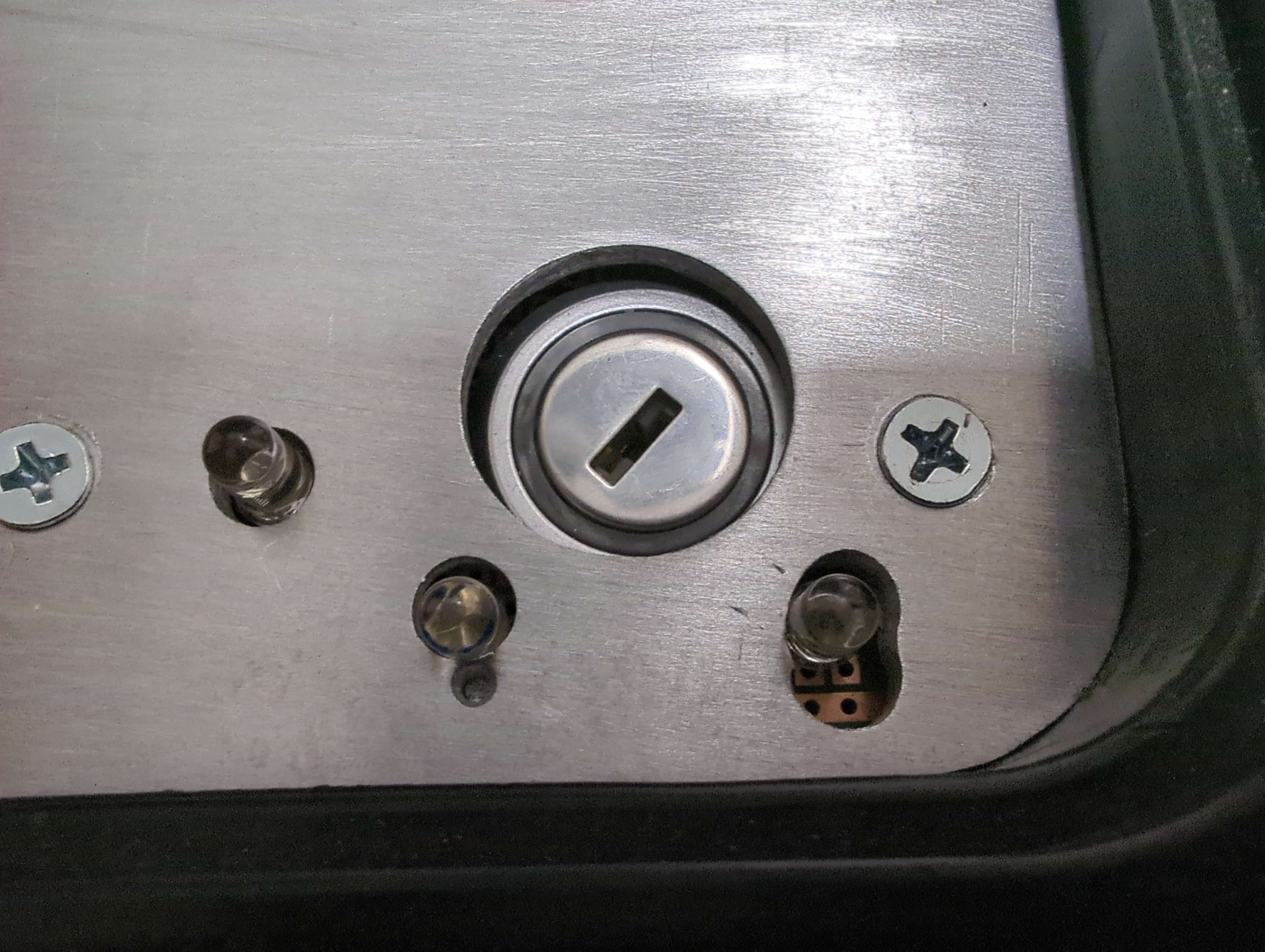
Rough-drilled and filed openings for the arm key and its status LEDs, functionally fine, cosmetically a crime scene.
The cover-up is the part I’d genuinely recommend: precision 3D printed labels over every opening. The printer holds tolerances my hand with a file can only dream of, so the printed labels sit crisply over the wobbly edges and hide them completely, while carrying the markings, the borders and the finishing that make the panel read as one deliberate object instead of a collection of holes.
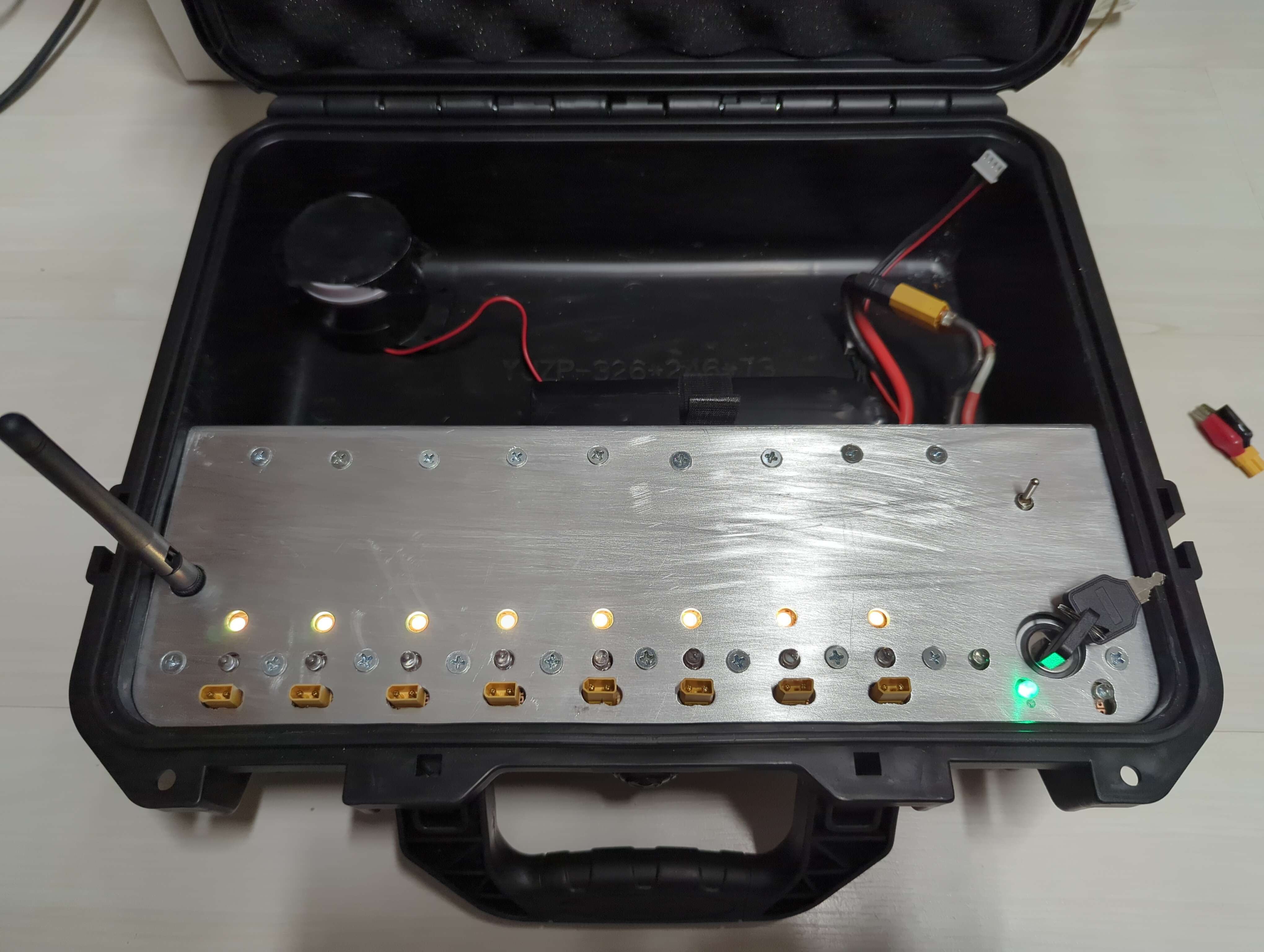
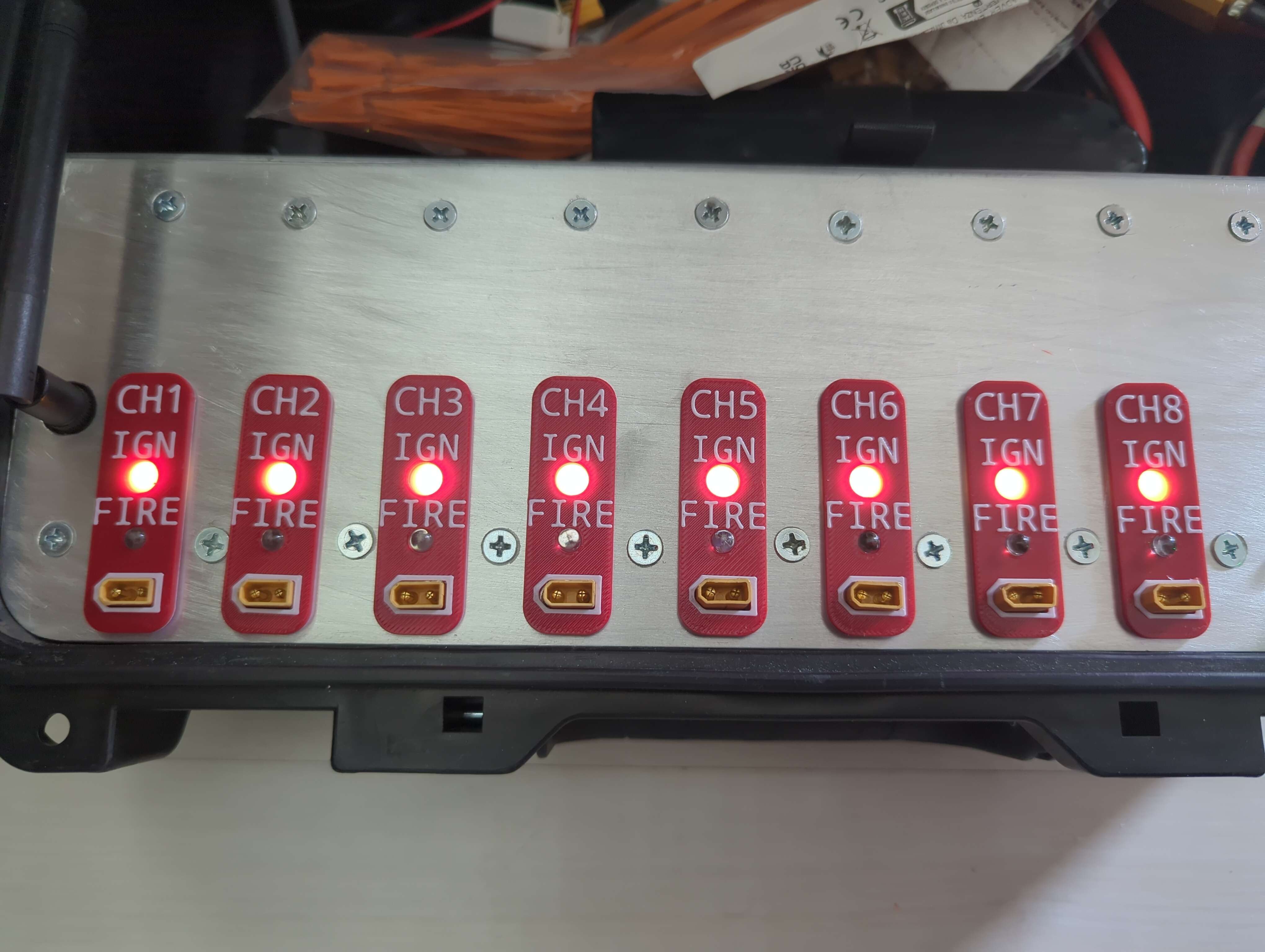
The same panel before and after, every sin of the file hidden behind printed precision.
Rough-cut the metal, print the perfection, put the perfection on top. It’s the same trick a good panel overlay achieves with a printed sticker, but printed plastic has actual thickness, so it also cleans up the edges of the cut-outs themselves.
Printed washers, or: how the lid closes#
The remote’s display, rotary encoder and power switch all mount through the front panel, and each of them needed to protrude exactly the right amount, too little and the display sits recessed, too much and the components poke out the back far enough that the case lid wouldn’t close. Off-the-shelf washers and spacers come in steps, and none of the steps were the right size.
So each of them got a custom 3D printed washer, dimensioned in CAD to fill exactly the gap the component actually needed. A printed spacer costs nothing to iterate: measure, model, print, test, adjust by a tenth of a millimetre, print again.
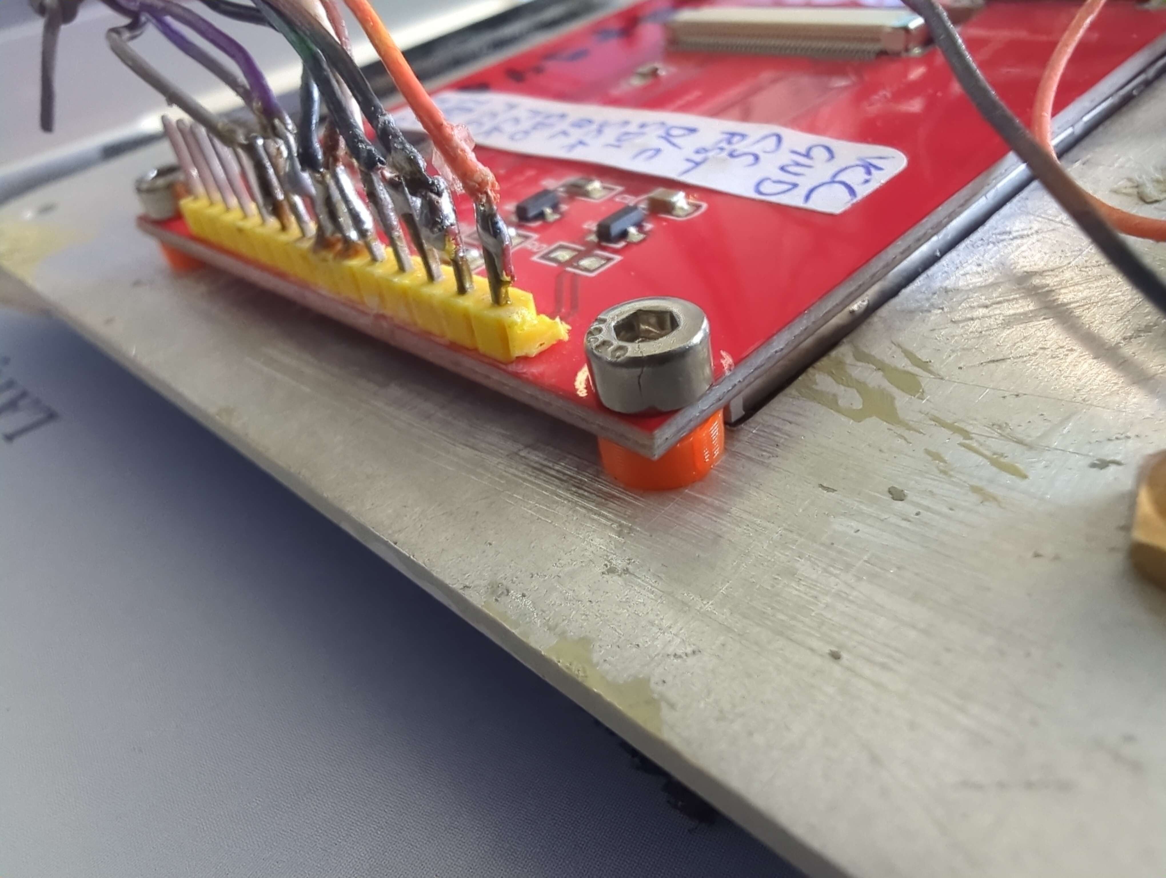
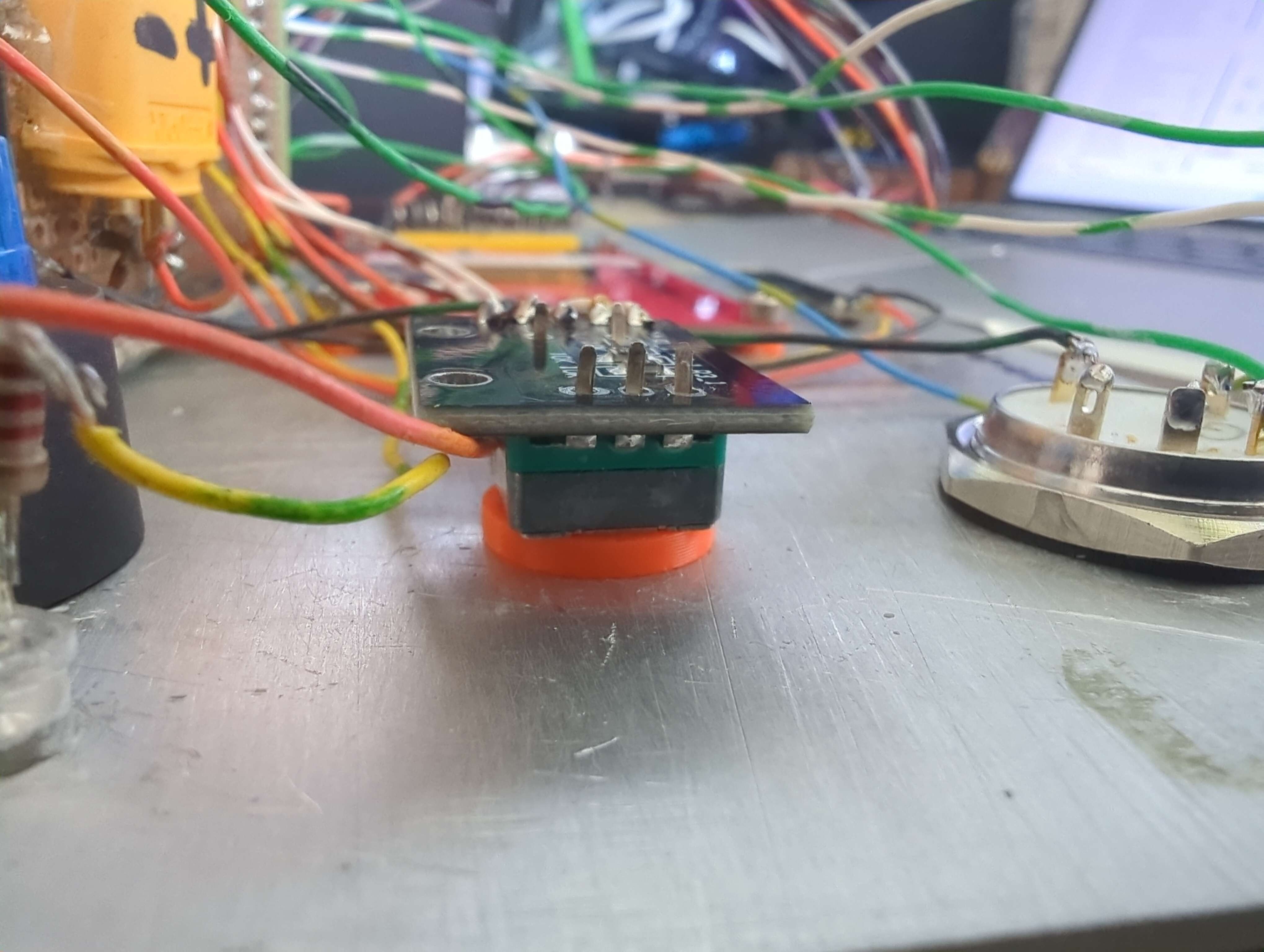
Custom printed washers under the display and the encoder, each one exactly as thick as it needs to be, and no thicker.
The remote panel: the K40 that couldn’t#
For the remote’s front panel markings I first tried laser engraving with my K40. The K40 is many things, but a precision marking laser it is not, the engraving came out inconsistent, blotchy and generally looking like crap on the painted aluminium. That attempt got sanded back completely and the panel repainted.
For the second attempt I switched to laser-printed waterslide decals: the labels and the logo printed on decal film, floated onto the repainted panel, and then clear-coated over to seal and protect everything.
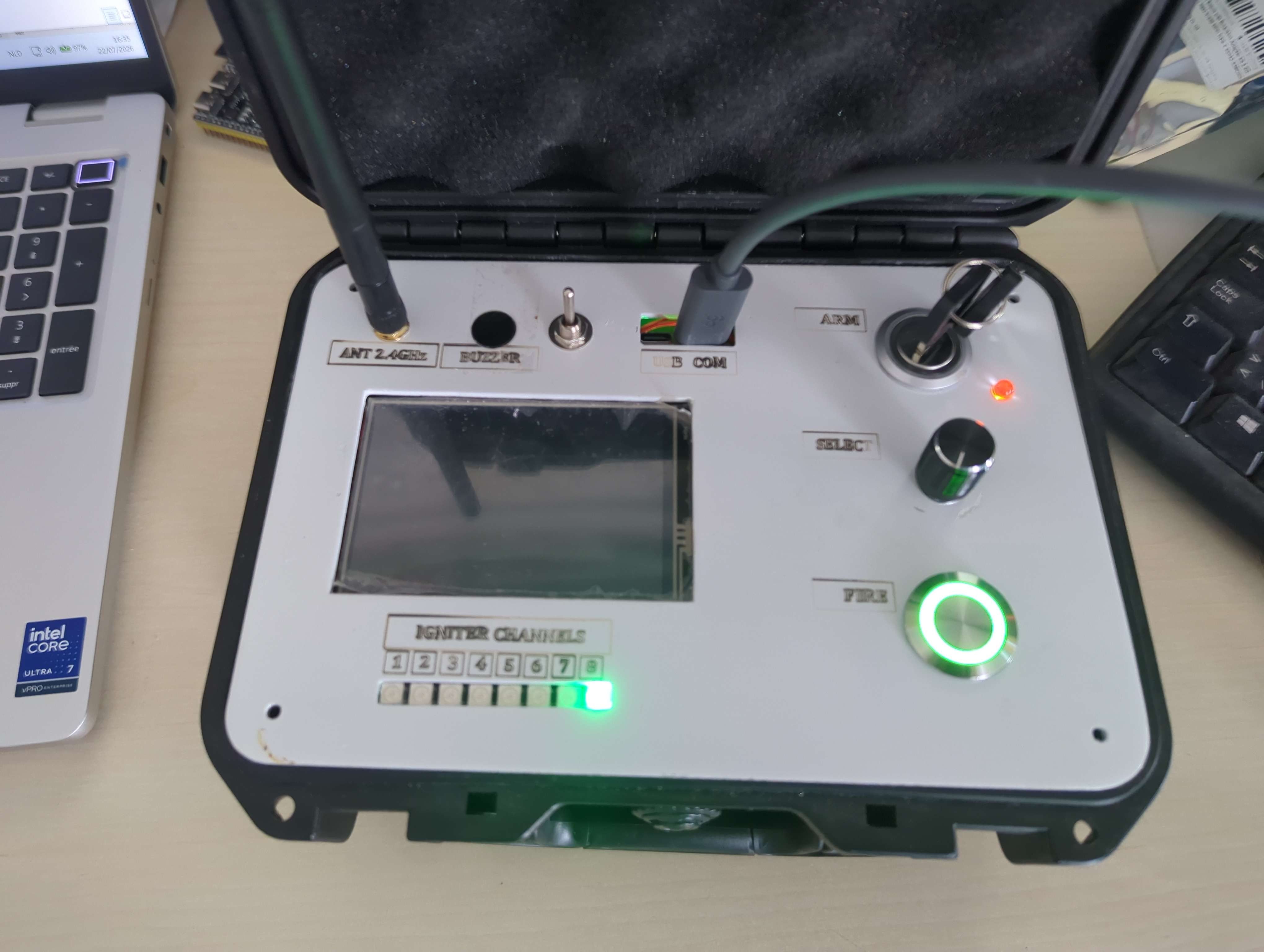
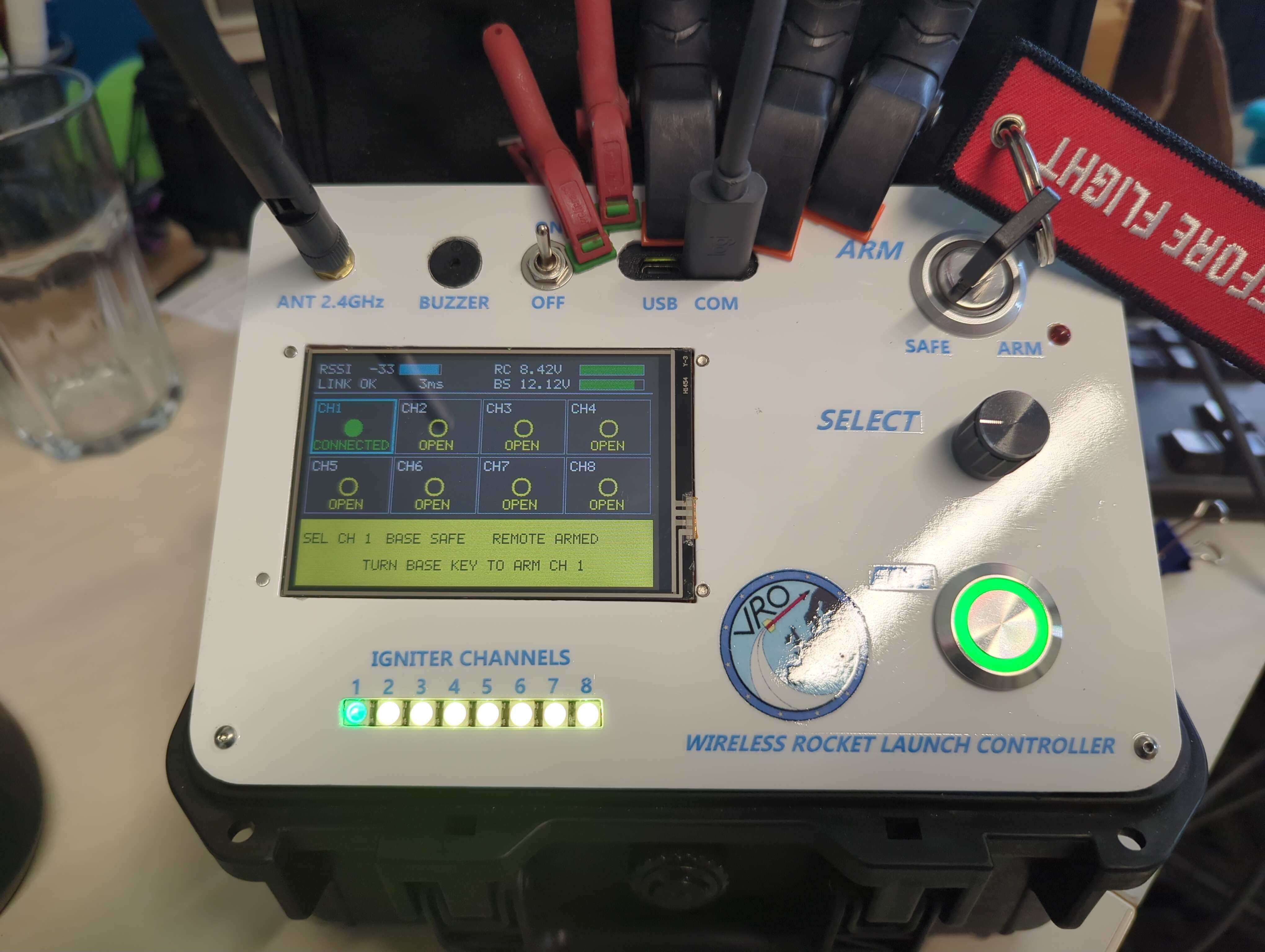
The remote during development with the old markings, and the finished panel with waterslide decals and clear coat.
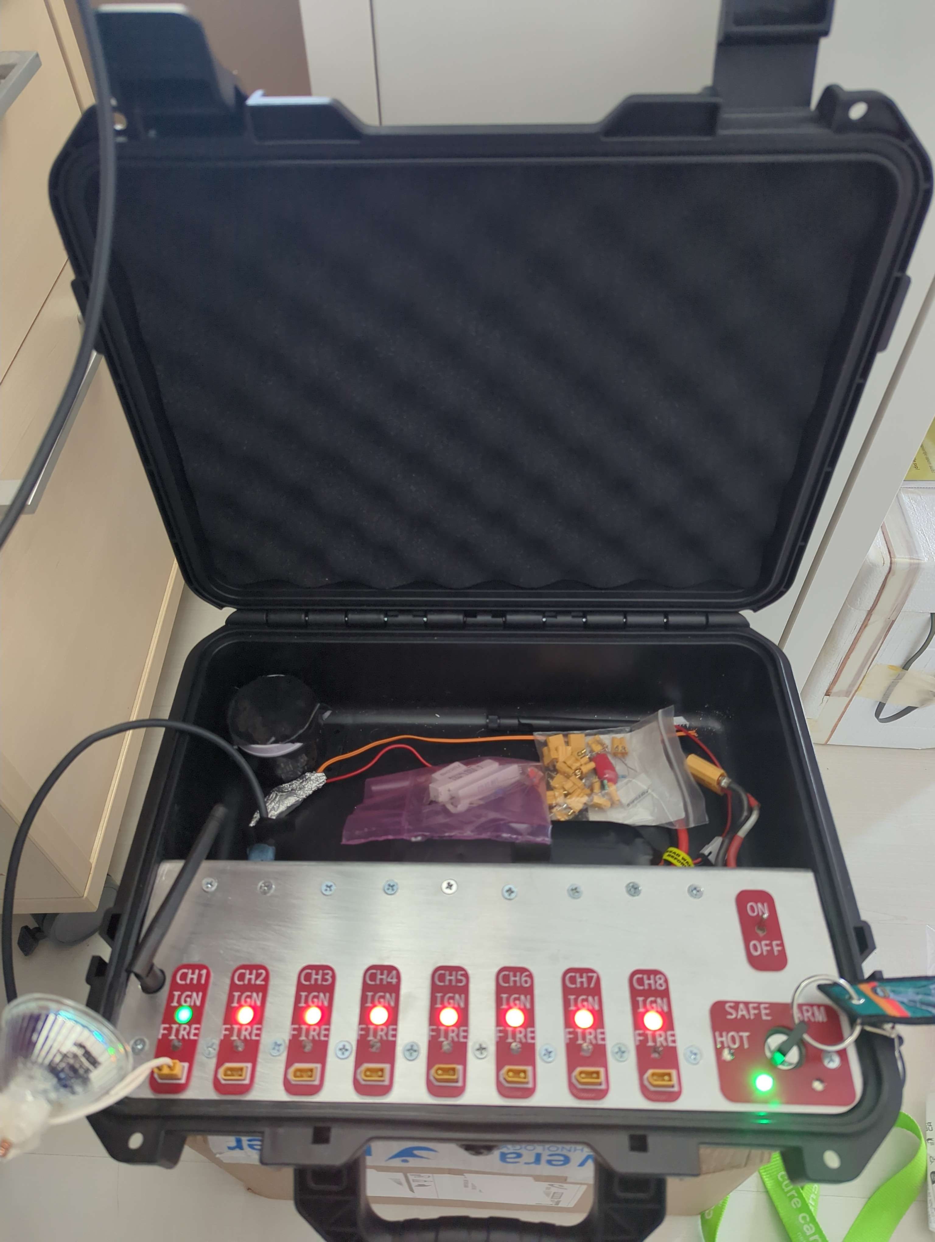
The finished base unit.
Waterslide decals are an old modelling technique that deserves to be better known in electronics: crisp text at arbitrary sizes, full colour if you want it, and with a clear coat over the top they’re durable enough for field gear. The K40 keeps engraving plywood. That it can do.
Testing without a launch pad#
How do you test a launch controller before trusting it at a launch? Two tricks carried this project.
First: a 12-volt, 50-watt halogen bulb is an igniter that survives. It draws current through the fire path exactly like an electric igniter does, and unlike an igniter it can be fired again and again. I fired all eight channels into one, channel by channel, nine pulses on a single power cycle, no reboots, no faults, and because only the channel actually carrying the lamp reads “connected”, the lamp lighting up on the right channel also proves the channel-to-relay mapping end to end.
Second: the unit tests compile the real firmware. The test suite builds the actual production source files on the host PC against mock ESP-IDF headers, 497 checks, no hardware needed, run before every build. The base’s safety state machine gets driven with event sequences while recording fakes note which relay moved and which siren pattern sounded. That matters because of a subtle trap I stepped straight into early on: a copy of the continuity classifier passed its own boot self-test for three review rounds while the real one drifted. A test that duplicates the code tests the duplicate.
War stories#
Every project keeps a few lessons that outlive it. These are mine.
The bug that had a loaded igniter’s name on it#
The most serious defect of the whole build never fired a shot. The fire pulse is timed by a hardware timer; when the one-second pulse completes, the timer’s alarm disables itself but the driver keeps running. So the second launch on a single power cycle hit a fatal error when the firmware tried to start the timer again, and the ESP32 panicked and rebooted with the arm relay and the channel relay still energised. An igniter on the pad would have carried full current through the entire panic-and-reboot interval.
It had never been noticed because no test had ever completed a fire pulse and re-armed on the same power cycle. Every test rebooted in between, politely resetting the landmine. A full-codebase review found it; I fixed it three ways (the timer is stopped on completion, stopped again before every start, and a start failure now latches the safe ERROR state instead of aborting), and wrote an automated two-cycle regression test that runs on every build since.
The general lesson: your test procedure inherits your assumptions. “Power-cycle it between tests” is itself a bug.
A display that redrew the world at 3.3 Hz#
The spec demanded the display refresh at 5 Hz minimum; mine managed 3.3. The panel and the SPI clock were innocent, the real problem was that every text field was repainted every frame whether or not it had changed, so the screen was rewriting all 153,600 pixels constantly. The fix flushes only the pixels that actually differ from a shadow copy of what the panel was last sent. On a steady screen that’s about 1,200 pixels per frame. And the display now runs at a steady 10 Hz.
I chose diffing over the more elegant-sounding “mark fields dirty when they change” on purpose: a missed invalidation leaves a stale pixel, and this particular screen displays the word ARMED.
The boot video that rebooted the remote (twice)#
Adding that splash video was supposed to be a cosmetic afternoon. It turned up two of the best bugs of the whole project.
The first: growing the band made the display task consistently overshoot its
frame deadline, and it turns out xTaskDelayUntil() doesn’t actually block
when the deadline has already passed. It just returns. Re-base to “now” and
the next frame overshoots identically, so a consistently slow task
degenerates into a loop that never yields once. The display task (priority 2)
starved the buzzer task (priority 1) on the same core, and the remote rebooted
on the task watchdog six seconds into every boot, like clockwork. A boot-screen
decoration cannot be allowed to silence the buzzer, that’s how the remote
talks to the operator when the screen is the thing that’s wrong, so the
display now yields explicitly after any overrun, bounding its share of the CPU
no matter how expensive a frame gets.
The second: giving register reads a slower SPI clock meant adding a second SPI device handle sharing the same chip-select pin. And ESP-IDF routes each device’s own hardware CS to the pin it’s configured for, so the second device silently stole the CS from the first. Every write ran with CS unasserted; the panel ignored its entire init sequence and sat there white, while the read path, the only thing being logged, worked perfectly and reported a healthy, correctly-identified panel. The standing rule that came out of it: a display clock change is judged by looking at the panel, never by reading the boot log.
Battery readings: take the median, not the mean#
Battery voltage is measured by bursting 33 ADC samples. Those are reduced with a median, not a mean, for a reason that only shows up on a noisy supply: a sample clipped at the ADC’s full scale can only bias a mean upward, making a flat pack look healthy. That is precisely the one direction a battery guard must never fail in. On my bench, a burst with 9 of 33 samples clipped read about 2 V high as a mean, and exactly right as a median.
The NeoPixel that lit up but did nothing#
The base unit’s status strip developed a “dead” fourth pixel. The actual fault was the third pixel: it rendered its own colour correctly but stopped forwarding data down the chain. Everything upstream of a WS2812 can look perfectly alive while everything downstream is dead. A pixel that lights is not evidence that it’s passing data, probe the data-out pin. I now keep a standalone diagnostic firmware in the toolbox for exactly this class of fault.
And one ESP32 gave its life#
Somewhere in the bring-up chaos, a base unit’s ESP32 died, traced to a 3.68 V rail it should never have seen. The devkit was replaced, the rail measured, and the corpse retired to a drawer as a reminder that “it was working yesterday” is not a datum. If anything good came of it, it’s that every unit since has had its rails checked before firmware, not after symptoms.
Built with Claude Code#
Regular readers know I do a lot of my building with Claude Code , and this project is the deepest that partnership has gone. It deserves an honest paragraph, because it changed the shape of the work.
The core of the method was spec-first. The functional specification, hardware, protocol, state machines, display, and a numbered test requirement for every safety claim, grew to fifty-some revisions and became the single source of truth. Code was reviewed against it, phase by phase; every review finding got tracked and re-verified; every phase closed with a written test report. The Critical fire-timer bug above? Found by a full-codebase AI review, not by me, and not by any bench test.
The division of labour that worked: I made every safety decision, what the interlock topology would be, what “safe” means, what the operator must hear and see. The AI was an implementation and review partner whose most valuable property was that it had read all of the code, every time, unlike any human I have ever worked with including myself. What it did not do was decide what mattered. That’s still the engineer’s job, and the moments where I had to overrule, redirect or simply say “no, that’s not safe enough” were where the real engineering happened.
The full deep-dive on the firmware, the radio protocol and the development process, Inside the ESP32 Rocket Launch Controller , is up next door for those who want the nuts and bolts.
Where it stands#
The controller is complete through its hardening phase, firmware 1.2.x, with the arming suite, fire tests and on-target display tests all closed out, and both units flashed and link-verified together after every change. It has fired all eight channels into the test load and burned real igniters on the bench. Since the hardening closed, the project has also picked up the splash video on the boot screen and been through a second full-codebase review. That one came back PASS WITH NOTES: the fire path verified sound end to end, every previously-fixed finding re-checked as still fixed, zero regressions, and two narrow gaps caught in the remote, both living in the half-second window while it waits for the base to acknowledge an arm or fire command. A display fault or a critical battery arriving in exactly that window could leave the remote entering its terminal error state without ever telling the base to stand down. Both were fixed in firmware 1.2.19 and both units flashed and link-verified together, as always.
It has not yet flown a launch day; the first one is planned for September 19th.
I’m deliberately honest about the remaining limitations: the batteries have no hardware undervoltage cut-off (protection is firmware-only, so a unit left switched on will flatten its pack), the battery dividers leave little ADC headroom at full charge, and the remote’s voltage-sense pin still needs its overvoltage clamp. None of these can fire an igniter; all of them are on the list.
And the standard disclaimer, in plain words: this is a personal project under active development. It fires pyrotechnic igniters. It is not a certified product, and if you build one, review the safety case yourself and follow your club’s and your country’s safety codes.
Resources#
- ESP32-RocketLaunchController on GitHub , firmware, host tests, bench tools, and the full documentation set
- The repository includes the functional specification, an operations manual (RLC-OPS-001) and a printable A4 field reference card
- VRO, Vlaamse Raket Organisatie
- My 2008 PIC16F88 rocket timer , for comparison, eighteen years of progress later
- Programming the Fri3d Camp badge with Claude Code , an earlier, smaller project with the same AI-assisted workflow