Inside the ESP32 Rocket Launch Controller: Firmware, Protocol, and Architecture
In the previous post I showed you the wireless rocket launch controller I built for VRO , two ESP32-S3 units, an encrypted radio link, and a handful of relays between an operator’s thumb and a pyrotechnic igniter. That post was the what and the why. This one is the how: the functional design, the decisions everything else derives from, the firmware architecture, the full catalogue of safety measures, the radio protocol, the sensing and display internals, and how the whole thing was tested and built. It’s long. That’s the point.
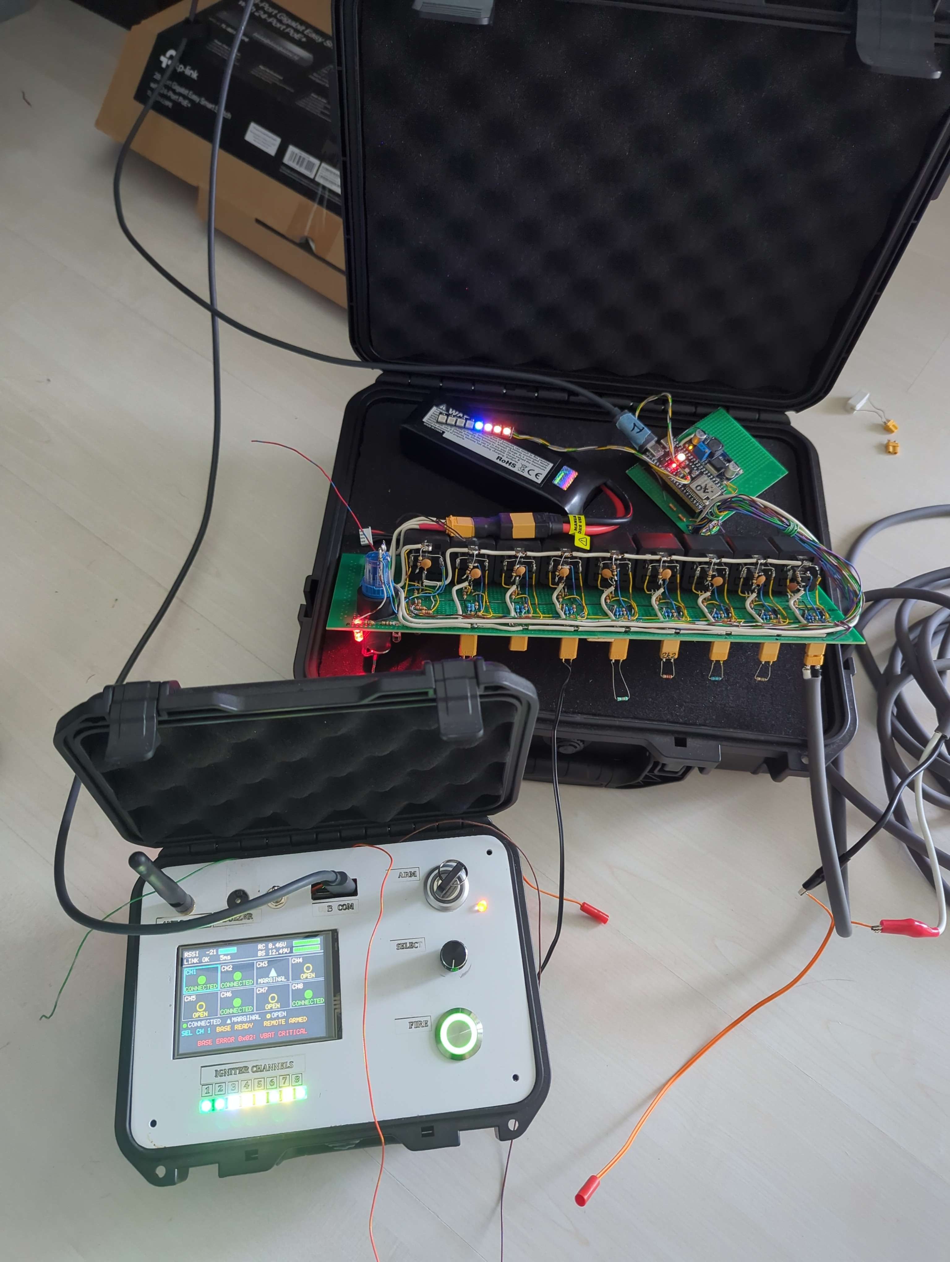
Both units on the bench during development.
The functional design, and the decisions that shaped it#
Architecture is the residue of decisions made early. Here are the five that shaped everything in this system, each one forced by a constraint, not chosen for elegance.
One LCO, two keys, one lanyard. The system is built for a single Launch Control Officer who owns the entire sequence. Both physical arm keys, the base’s and the remote’s, live on the LCO’s lanyard. That sounds like an inconvenience; it’s actually the safety concept. Because the base key is on the operator’s neck, arming the pad requires physically walking to the pad, turning the key, and walking back. Nobody can arm a rocket from the firing point, and nobody can fire one without having chosen to be the only person in the loop. The walking is the interlock.
Fire is a level, not a command. The fire button does not send a “fire” event; it asserts an ongoing intent. The remote transmits CMD_FIRE every 200 ms for as long as the button is held, and the base will only energise the igniter if it has received one within the last 500 ms. Release the button, or let the link drop, or let a burst of packets die. And the authorization evaporates within half a second. This single decision ripples through the whole design: no command can “latch” a firing, every radio failure mode degrades to stop, and the operator can always abort by doing the most natural thing in a moment of doubt: letting go.
Two breaks in the fire path, and the key isn’t one of them. Current reaches an igniter only through the arm relay and the selected channel relay in series. The arm key switch deliberately does not sit in the fire path, it couldn’t carry igniter current anyway, but in the arm relay’s coil drive, in series with a firmware-driven MOSFET. That makes a hardware AND gate: the coil can only energise if the key is turned AND the firmware commands it. With the key in SAFE, no software fault at all, not a stuck GPIO, not a rogue radio frame, can put current in the fire bus, because there is no current available to close the first break. It’s a stronger guarantee than a third contact in the fire path would give.
The base is the safety authority. The remote suggests; the base decides. Every guard condition, key position, continuity, battery, link quality, is evaluated at the pad, milliseconds and a radio hop away from the relays it protects. The remote’s role is operator interface: display, sounds, button handling. If someone replaced the remote with a malicious transmitter that knew the keys, they still could not talk the base into arming without the physical key being turned at the pad.
Everything fails toward safe, and says so. Relays energise-to-close, with gate pulldowns holding them off through boot. Inputs are active-low, so a broken wire reads as safe. Unknown state is displayed grey, never green, green is a positive claim that the pad may be approached. Every refusal the system can make produces a sound and a message. And a fault the firmware can’t reason about latches an ERROR state that only a physical power cycle clears, the system would rather be useless than clever.
One more practical decision: both units build from one codebase. The
same repository, the same source files, two sdkconfig files selecting base or
remote. The build scripts refuse to produce a binary unless the expected
unit’s app_main symbol actually landed in it. Every shared behaviour,
debouncing, battery sampling, the radio layer, exists exactly once.
The specification as the source of truth#
Before this project I’d have called a functional specification bureaucracy. I’ve changed my mind. The FSD, functional specification document, grew to 56 revisions and became the single source of truth for the machine: hardware topology with GPIO assignments and resistor values, the message format down to byte offsets, both state machines transition by transition with their guard conditions, every buzzer pattern, every display screen, and a numbered test requirement (T-A01 through T-S19) for every safety claim the design makes.
The rule that made it work: code is reviewed against the document, never against memory. When a review finds a mismatch, one of them is wrong and gets fixed, and the revision history records which and why. Reading back through those 56 revisions is reading the project’s actual history: the arm relay redesign in v1.13 when we realised the key switch couldn’t handle igniter current; the pre-fire countdown raised from 2 s to 5 s in v1.36 after a test proved you cannot disconnect an igniter in two seconds; the v1.47 entry documenting that a buzzer “nudge” could silently delete an alarm.
What stayed out of the spec mattered too: implementation details that live happily in code comments (loop structure, buffer sizes) would have drowned it. The test: if getting it wrong could energise a relay, silence an alarm, or mislead an operator, it belongs in the spec. If not, it doesn’t.
Firmware architecture#
Both units run ESP-IDF on FreeRTOS, with a fixed-priority task set that encodes one rule: safety-critical work outranks cosmetics. The radio receive worker sits at priority 8 so its own consumers can never starve it. On the base, the arm-switch/key-sense monitor runs at 7; on the remote, the fire button at 7. The link manager at 6, continuity sampling at 5, the state machines at 4. And the siren, display, buzzer and LEDs down at 1–2, pinned to the second core so a heavy screen repaint can’t even contend for the safety core. The watchdog is fed from the highest-priority safety task, not from idle.
| Base task | Prio | Remote task | Prio |
|---|---|---|---|
espnow_rx (radio receive) | 8 | espnow_rx | 8 |
arm_switch_task (key + arm sense) | 7 | fire_button_task | 7 |
rlc_link (heartbeat, validation) | 6 | arm_switch_task, rlc_link | 6 |
continuity_task | 5 | state_machine_task, cmd_fire_repeat_task | 4 |
state_machine_task (FSM) | 4 | battery_task, encoder_task | 3 |
battery_task, status_update_task | 3 | display_task | 2 |
siren_task | 2 | buzzer_task, rgb_led_task | 1 |
rgb_led_task | 1 |
The state machines are single-task-owner: all state mutation happens on one task, everything else reads through getters. There are no mutexes in the safety path because there is no shared mutable state to lock. Events arrive by queue; the FSM processes them in priority-of-arrival order and its transitions are pure functions of (state, event, guards).
A subtle but important detail sits in the timer plumbing: the fire pulse is
timed by a hardware GPTimer whose ISR callback does exactly one thing,
xTaskNotifyFromISR() to the state machine task. No GPIO writes in
interrupt context, no mutex acquisition, no globals read behind the
scheduler’s back; the channel number travels as the notification’s context
argument. Everything that touches a relay happens in task context, in one
place, in order.
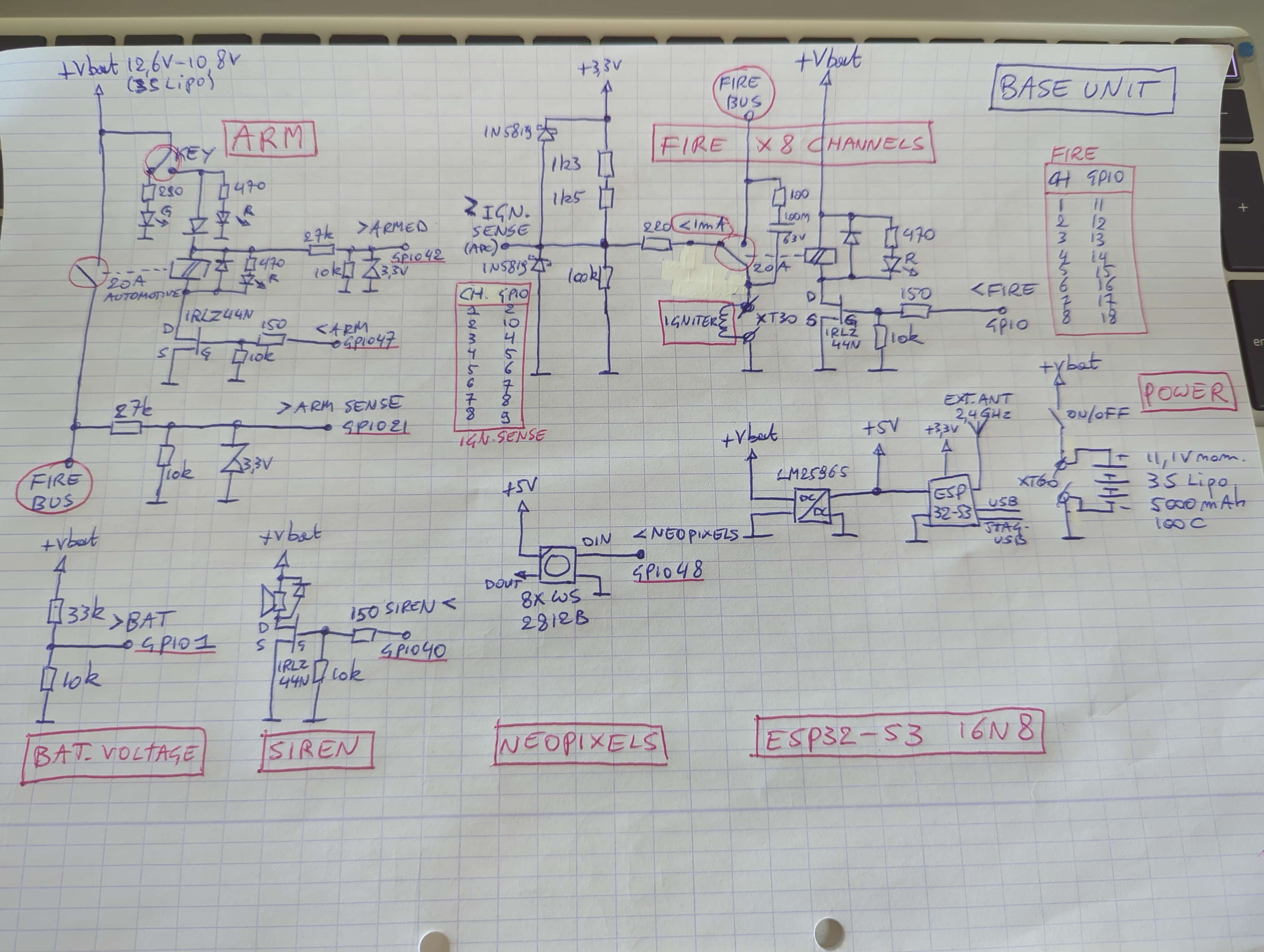
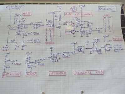
The base unit schematic as drawn in the specification, every GPIO assignment and resistor value lives in the document, not in tribal knowledge.
After the build, both units also got proper drawn schematics. They are generated
from the FSD and the as-built record by scripts in the repository
(tools/base_schematic.py and tools/remote_schematic.py), so they can be
regenerated after any hardware change instead of drifting away from reality.
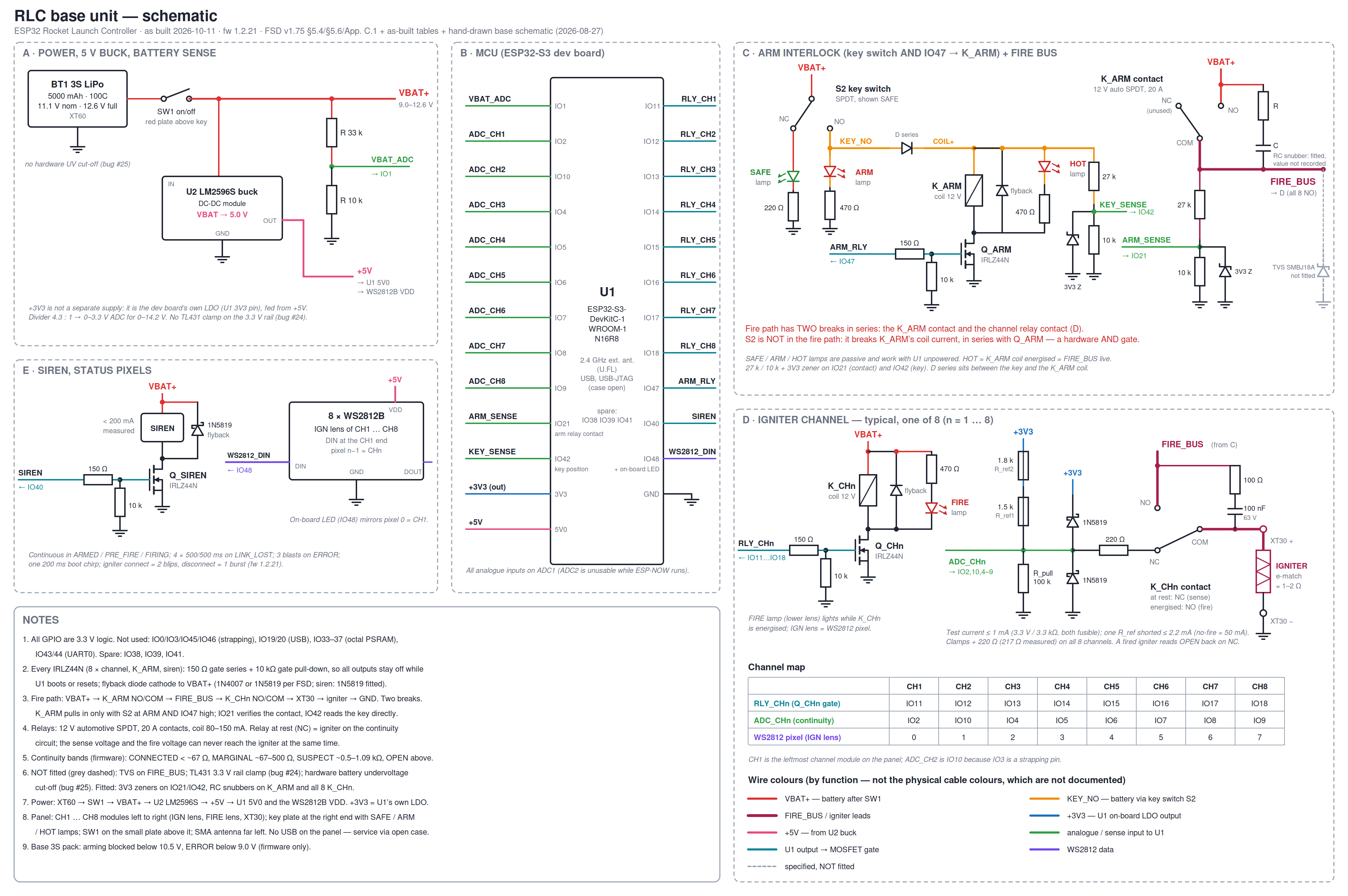
The base unit schematic, reconciled against the built unit: power, MCU, the arm interlock and fire bus, a typical igniter channel, and the siren and pixel strip.
Drawing the base against the hardware it claims to describe caught real discrepancies. The igniter sockets are XT30, not the XT60 the spec said. The 3.3 V zeners on the key-sense GPIOs are fitted. The continuity reference resistor the hand sketch labels 1k3 turned out to be a 1k8, the known-load measurements from August fit 3.3 kΩ total and not 2.8 kΩ at all. The FSD was corrected in each case; that is the document keeping its authority by losing arguments to the bench.
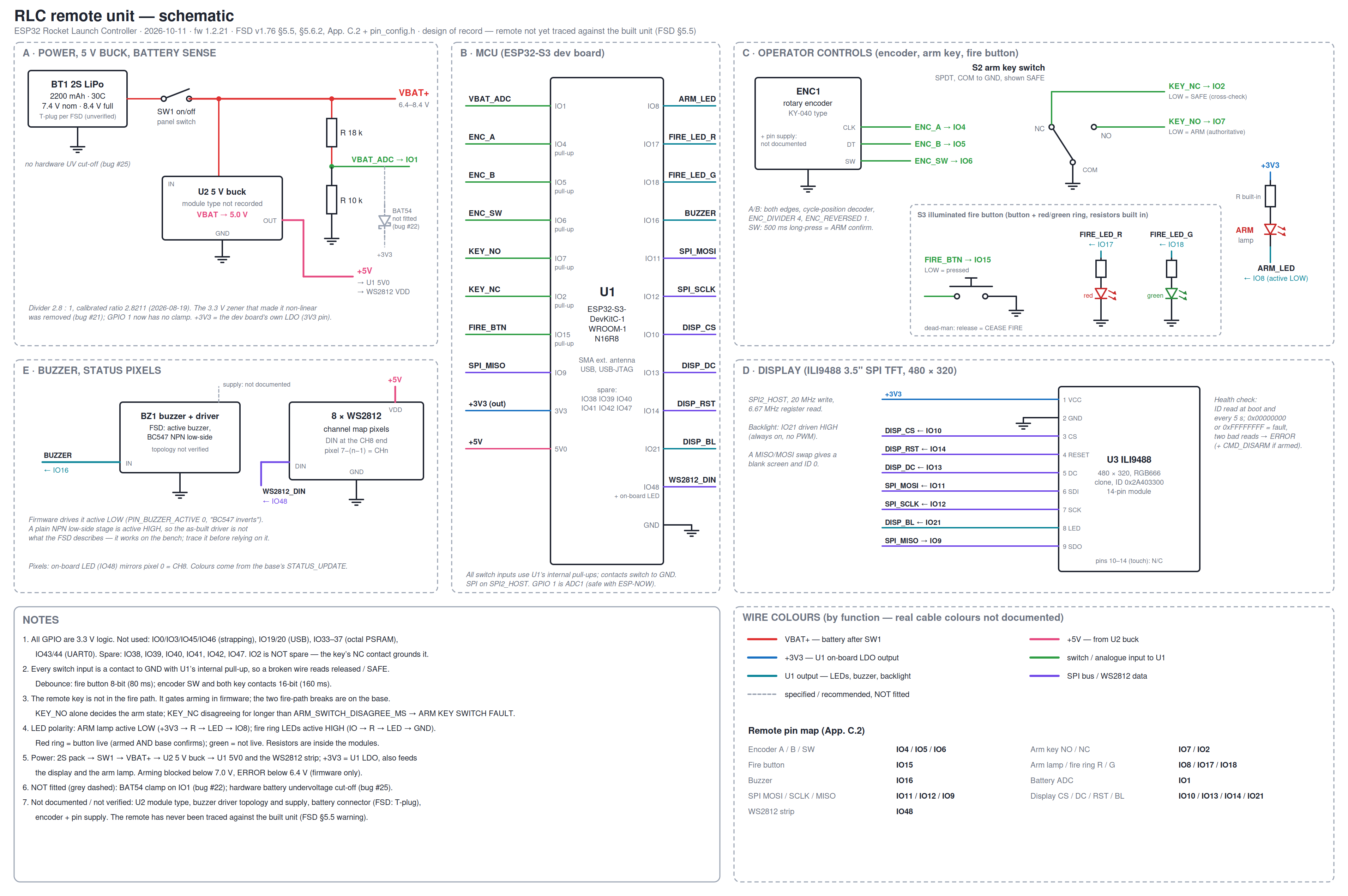
The remote unit schematic, design of record: the remote’s I/O has never been traced against the built unit, and the drawing says so on its face.
The remote drawing is honest about a weaker position: no hand drawing of it ever existed, so it follows the FSD and the pin configuration headers, and it carries the caveat that the remote panel has never been reconciled against the built unit. Where something is unverified, the buck module type, the battery connector, the buzzer driver stage. It is drawn and labelled as unverified rather than guessed. One correction came out of drawing it: the remote has no separate 3.3 V buck converter; a 5 V buck feeds the devkit’s 5V0 pin and the WS2812 strip, and 3.3 V comes from the devkit’s own LDO.
The safety measures, a full catalogue#
This is the section the project exists for. Every measure below has a “why” (which failure mode it defends against) and a “how”. They’re grouped by layer, because defence in depth only works if a single fault has to defeat more than one kind of thing.
Fire path hardware#
- Two series breaks. Arm relay plus channel relay; both must close. Either one welding shut alone ignites nothing.
- The key-in-coil-drive AND gate. IRLZ44N MOSFET in series with the key switch, both in the arm relay’s coil path. Key in SAFE ⇒ no coil current exists ⇒ no software fault can close the first break. The gate’s pulldown holds the MOSFET off through every boot and reset state, so there’s no window during startup where a floating pin could energise anything.
- Relay feedback (“arm sense”). The arm relay’s COM output is read back on its own GPIO through a divider. The base never assumes the relay obeyed, it verifies the contacts actually closed within 200 ms, and it detects the opposite fault too: contacts closed while the relay is commanded off is a weld, which latches terminal ERROR immediately, because it means current can reach the fire bus with nothing commanding it. A slow or ageing relay gets one free retry (a single verify timeout is a refusal, not a fault); two in a row is a wiring fault and the base stops offering to arm.
- Energise-to-close everything. Loss of power, brown-out, reset, every one of them physically opens the fire path.
- Contact protection. RC snubbers across every relay contact and clamping diodes on every sense line, because relays switching igniter loads are electrically rude and the fault that eventually bites you is the one that corrupts a sense input into lying.
Sensing#
- ~1 mA continuity sensing. The continuity test current is limited to about a milliamp, two orders of magnitude below anything that could heat an igniter. Sensing is analogue (ADC, 64-sample oversampling per channel) and classifies each igniter as CONNECTED, MARGINAL or OPEN.
- Active-low inputs. A broken wire, a corroded connector, a unplugged switch, all read as “safe”, because safe is the de-energised, grounded state of every input.
- Battery monitoring as an arming guard. Both packs are measured (33-sample bursts, reduced with a median, not a mean, a sample clipped at the ADC’s full scale can only bias a mean upward, making a flat pack look healthy, which is the one direction a battery guard must never fail). Below the arming threshold, ARM is refused; below the critical threshold, the unit latches ERROR.
Firmware guards#
- Ten arming guards. Before the arm relay may close: the key-switch sense input reads ARMED (a dedicated GPIO reading the key directly, not the relay feedback, which could only confirm a relay that’s already closed); the channel’s continuity band is not OPEN; the channel is in range 1–8; no other channel is armed; the frame’s integrity CRC is valid; the session token is valid; the sequence number is not a replay; the base battery is above threshold; the link is not degraded; and the link is established at all. Any failure is a NACK with a reason, not silence.
- The non-blocking verify window. During the 200 ms arm-verify window the FSM does not block: a disarm, a cease-fire, key-off, battery-critical or link-loss arriving mid-window cancels the pending arm and de-energises the relay. The system never completes an arm “behind the operator’s back”.
- The dead-man scheme. CMD_FIRE repeats every 200 ms while held; a stale authorization (>500 ms) aborts; the pre-fire-to-firing transition additionally requires a fresh frame within 1 s and a non-degraded link (ping failure rate ≤ 30 % of the last 10). At the moment the igniter energises, a second, independent re-verification of key position and arm sense runs, defence in depth on the exact transition that matters.
- Asymmetric debouncing. The fire button registers a press after 80 ms but a release after only 20 ms. Symmetric debouncing is right for a sensor and wrong for a dead-man switch: a missed release extends a firing the operator has ended, the dangerous direction, while a spurious early release merely aborts, the safe direction. So the release path is tuned to be the more sensitive one.
- Auto-disarm and level backstops. Ten seconds armed without a fire command disarms. Continuity loss during armed handling is caught both as an edge event and by a periodic level re-check (~50 ms), so a break that happens inside a debounce window can’t slip through with no edge left to report.
- Timer discipline. The fire timer is stopped on completion, stopped before every start, and a start failure latches ERROR instead of aborting. That triple is a direct scar: a panic on the second fire cycle of a power cycle once left both relays energised through the entire panic-and-reboot interval (that story is in the previous post).
- Terminal ERROR. Unrecoverable faults halt the system rather than attempting self-healing. The ERROR state requires a physical power cycle by design, an autonomous recovery from an unknown fault state is exactly the kind of cleverness a launch pad doesn’t want.
The operator interface#
- No silent refusals. Every refusal, abort and failure an operator can trigger produces a sound and a display message. A beep-only refusal is indistinguishable from a button that didn’t register. And the natural response to apparent non-response is to press again, which is the wrong instinct at a pad. Even the base in terminal ERROR answers (NACK “BASE IN ERROR”) instead of silently discarding, so the remote can name the specific fault it already knows about.
- The pad siren sounds continuously from ARMED through firing, an audible boundary around every state where the fire bus is live. It actually needed firmware help too: the siren has its own internal modulation, and the original short “armed” chirp fought it into near-inaudibility. Continuous drive is louder and simpler.
- State tones that can’t be confused with alarms. While armed, the remote sounds a sparse ~0.8 Hz heartbeat; through the countdown and pulse an insistent ~4 Hz pattern. Both fault alarms are ~2.5 Hz, deliberately between the two state tempos so “the pad is live” can never sound like “something is wrong”.
- Passive status lamps. The base’s HOT lamp, “arm relay live”, is an LED wired across the sense circuit, no firmware involved. It works with the ESP32 unplugged, which is the only time you genuinely need it.
- The status band. A coloured strip across the bottom of every remote screen naming the fire-path state in words: green SAFE, yellow one key turned, orange READY TO ARM, red ARM RELAY LIVE, flashing red/amber RELAY WELDED, grey STATUS UNKNOWN. Grey, never green, whenever the state is unknown, because green is a positive claim the pad is safe to approach, and absence of information must not produce it.
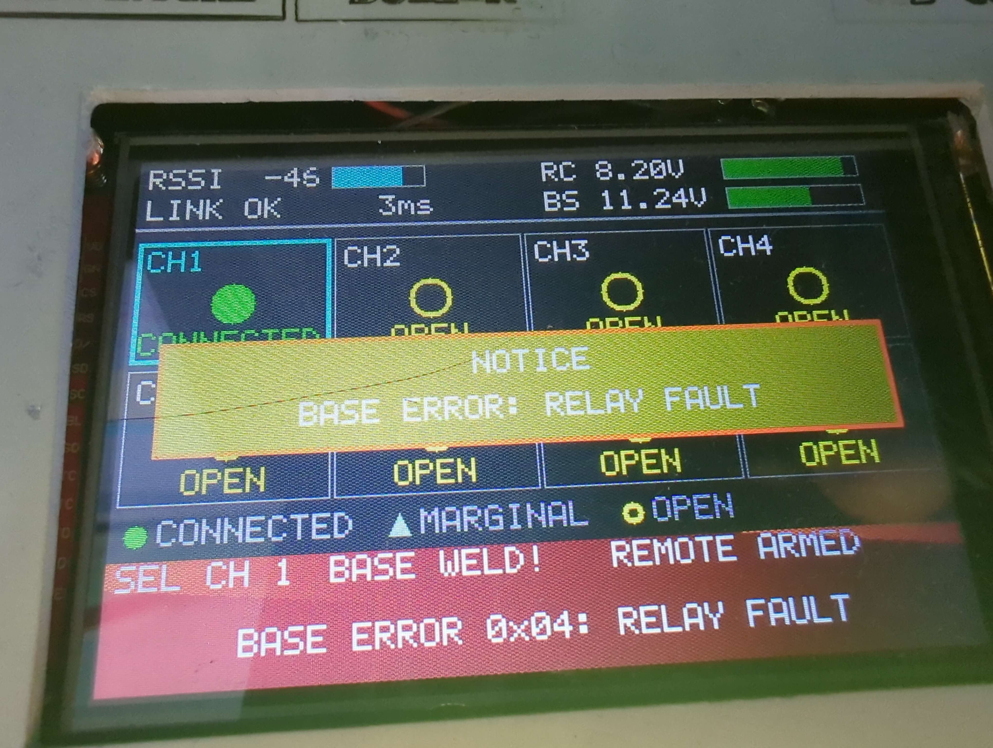
A fault named on screen, with a reason, never just silence.
The link#
Encryption, an application-layer integrity check, replay protection, strict firmware version matching, 1.5 s link-loss detection and fail-to-safe on every radio failure mode, each gets one line here because the next section covers the machinery properly.
And honesty is part of the catalogue: the system has no hardware undervoltage cut-off on either battery (a unit left switched on will flatten its LiPo into the damaged region), the battery dividers leave little ADC headroom at full charge, and the remote’s voltage-sense pin still needs its overvoltage clamp. None of these can fire an igniter; all of them are tracked in the project’s open-items list, because a safety case that hides its gaps isn’t one.
The radio protocol#
The link is Espressif’s ESP-NOW: connectionless, peer-addressed frames over Wi-Fi radio at 1 Mbps, fixed channel (11 by default, channel 1 is a traffic jam at any launch event), with external antennas on both units. Measured range: 430 m at −91 dBm with the base on the ground, with 5–8 dB of margin left at that distance. An earlier run in the same geometry read 200 m at −93 dBm and, extrapolated with the two-ray fourth-power law, predicted the link would die around 250 m, the second test beat that by 15 dB, so the model is a pessimistic bound rather than a prediction. Near the ground the link is still two-ray-limited rather than free-space: raise both ends to 1.5 m and the same hardware clears a kilometre.
Every message carries a 12-byte header: protocol version, message type, payload length, a monotonically increasing 32-bit sequence number, and the session token. Eleven message types: link establishment (LINK_REQUEST / LINK_ACK), heartbeat (PING/PONG every 500 ms), the four commands (ARM, DISARM, FIRE, CEASE_FIRE), and three responses (STATUS_UPDATE, CMD_ACK, CMD_NACK with a reason code).
Security is layered, and each layer has a job. ESP-NOW’s AES-128-CCM encryption with per-peer keys is the security boundary against an adversary. On top of it, every command carries a CRC32-C, the Castagnoli polynomial, hardware-accelerated on the S3, computed over the entire message plus a shared 16-byte key, header included, so a corrupted message type can’t turn a DISARM into a FIRE by bit-flipping. That CRC is explicitly not authentication; it’s there because the thing that most threatens this link in practice is not a spy but a bug, and it catches those. Replay protection is structural: sequence numbers reset at every link establishment, must strictly increase, and on overflow the sender re-links rather than wraps; the session token is freshly random per link-up, and a new LINK_REQUEST atomically invalidates the old token so no delayed frame from a previous session survives the handover.
The keys themselves have a story worth telling because it’s the most honest
lesson in the project: they shipped for weeks as literal ASCII placeholders
committed to a public repository, guessable without reading the source.
They’re now generated per-installation by a script into a gitignored header,
the build fails with an instructive #error if real keys are missing
(because a silent fallback to a default is exactly how the placeholders
survived unnoticed), and a pre-commit hook refuses any commit that stages a
key under any path. The old keys stay public forever, git history has them,
and the mitigation is that they’re now meaningless.
Strict version matching closes the loop: both units must run byte-identical firmware versions or the link is refused outright, because a protocol constant changed on one side is a protocol the other side misinterprets. This produced my favourite development quirk: the mismatch is latched, so flashing the two units back-to-back always leaves the first-flashed one sulking on a FIRMWARE MISMATCH screen until you reset it, the symptom looks like a bug and is actually the safety rule working.
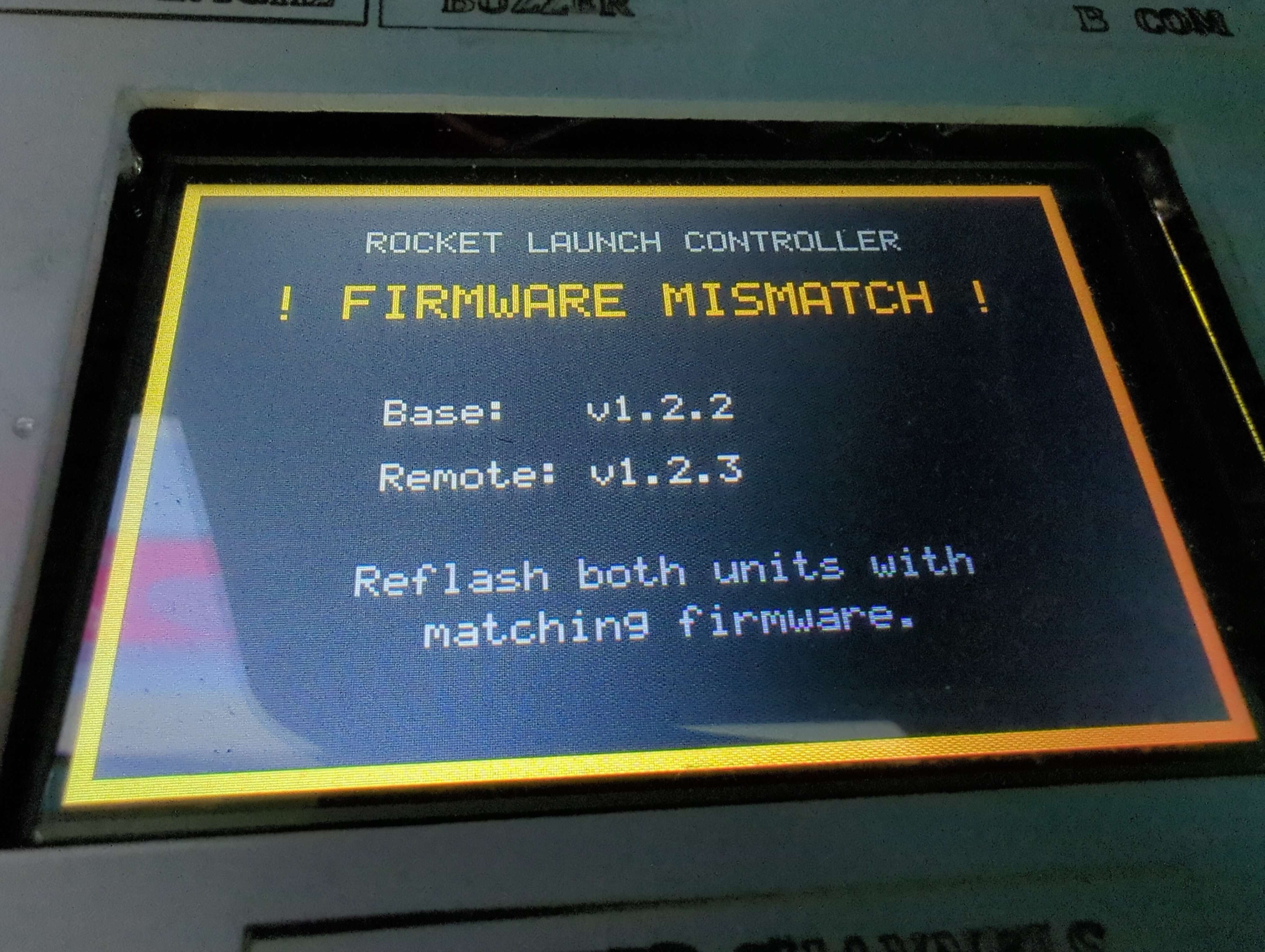
The version-mismatch screen, annoying by design.
Continuity sensing and the display#
Continuity is measured the careful way: a ~1 mA current-limited source per channel through the igniter, into an ADC, 64 samples oversampled per channel every 100 ms, classified into bands. The original design specified four bands including SHORT; measurement killed it, at 1 mA, a dead short and a healthy 1.5 Ω igniter differ by about a millivolt, the same magnitude as the noise floor. A SHORT band would have been a random number generator with confidence, so it was merged away and the surviving band named CONNECTED rather than GOOD: it means current can flow, not that the igniter is sound.
The display is a 480×320 ILI9488 over SPI, driven from a full framebuffer in PSRAM. Getting it from its first working state (3.3 Hz refresh) to the specified 10 Hz was a lesson in honest measurement: the panel and SPI clock were never the bottleneck, the code was repainting every text field every frame whether or not it had changed. Now the render pass computes a dirty bounding box, and the flush diffs that box row by row against a shadow copy of what the panel was last sent, transmitting only the changed spans: about 1,200 pixels per frame on a steady screen, out of 153,600. I chose whole-frame diffing over per-field invalidation on purpose: a missed invalidation leaves a stale pixel, and this screen displays the word ARMED.
The interface rules the display enforces: no text smaller than 12×16 px per character (anything smaller proved unreadable at arm’s length outdoors); continuity shown as shape-plus-colour so the grid survives colour vision deficits; and the status band across every screen, described above.
A boot screen that plays real video#
Late in the project the boot splash went from a drawing to actual footage: the two Falcon Heavy side boosters landing at LZ-1, played as a 480×160 band across the top of the panel while the remote hunts for the base. Getting there taught me more about the hardware than any feature that “mattered”, so it’s worth the detour.
The asset is a JPEG frame sequence living in its own 2 MB flash partition, decoded on the fly and memory-mapped, deliberately not embedded in the firmware binary, so footage can be re-cut and reflashed without ever touching the image that runs the fire path. Every failure is non-fatal by design: no partition, a blank or corrupt asset, wrong dimensions, a frame that won’t decode, each ends with a plain dark band and a remote that boots normally.
The interesting engineering was the budget, and the budget lied at first. The
original analysis said “decode cost and flash space were never the constraint,
the wire is”, true at the original 480×80 band, and false the moment it grew.
flush() transmits by polling, so transfer time is core time: measured at
480×128 and 20 MHz, a frame cost 99 ms, of which only 74 was the SPI transfer
itself, the rest was the per-row diff, bounce copies and shadow updates
(decode 12 ms, blit 9 ms, neither ever mattered). The budget turned out to be
CPU, not wire. The fix was counterintuitive: run the clip at 5 Hz, below the
display’s 10 Hz, with early-outs so frames where the video hasn’t advanced
cost almost nothing, 73 ms average, ~120 ms on the frames that do.
Two of the best bugs of the project fell out of this work. One:
xTaskDelayUntil() does not guarantee a yield. It returns without blocking
when its deadline has already passed, so a consistently slow frame
degenerates into a free-running loop. The display task starved the buzzer task
on the same core and the remote rebooted on the task watchdog six seconds into
every boot. The display now yields explicitly after any overrun, a safety
property, not a nicety, because the buzzer is the operator’s channel when the
screen is the thing that’s wrong. Two: the SPI clock was raised to 40 MHz
(above the ILI9488’s specified 20, sustained fine by the fitted clone) and
register reads got their own second device handle at 10 MHz, because the
panel’s read cycle is 150 ns against a 50 ns write cycle, and at 40 MHz the ID
read back stably wrong. Stable corruption is the dangerous kind: the health
check compares each read against the boot read, both ends were wrong the same
way, and it kept reporting a healthy panel while reading noise. The same
second-device trick had already bitten once in an earlier attempt, two devices
configured on the same CS pin means the second steals the pin’s hardware CS
from the first and the panel sits white while the logs say healthy. So CS is
now driven manually on both devices. The standing rule from all of it: a
display clock change is judged by looking at the panel, never by the boot
log.
The title and club credit are drawn over the footage, and white-on-video is
not white-on-black: the text is outlined, and the footage is graded and
dimmed under two ramped “scrims” baked into the asset itself, which makes
the firmware’s scrim geometry a contract with mkvideoband.py, the Python
tool that cuts the band from source video. A second tool re-times a band
without re-encoding, because sampling a clip at a different rate changes the
tracking, and a re-tune is not a re-time.

The band as it ships: 480×160 of real footage with the title and credit overlaid, and the connection progress below it.
Testing philosophy#
Three ideas carry the whole test effort.
Test the real code, not a copy of it. The host test suite compiles the
actual production .c files on a PC against mock ESP-IDF headers, 497
checks, no hardware attached, run automatically before every
firmware build (the build scripts refuse to proceed if it fails). The base
FSM test is the crown jewel: it links the real state machine against
recording fakes for the relays, siren, timers and link, injects event
sequences, and asserts what the FSM did, which relay moved, which siren
pattern sounded, which NACK reason went out. That’s how the arming guards,
the dead-man aborts and the two-fire-cycles-per-power-cycle regression are
covered without a launch pad. And the reason it links real sources is a
scar: a duplicated continuity classifier passed its own self-test for three
review rounds while the real one drifted. A test that mirrors the code tests
the mirror.
A halogen bulb is an igniter that survives. A 12 V 50 W lamp draws current through the fire path exactly like an electric igniter and can be fired indefinitely. All eight channels were qualified into one lamp, nine pulses on a single power cycle, no reboots. And because only the channel carrying the lamp reads CONNECTED, the lamp lighting on the right channel proves the channel-to-relay mapping end to end. Real igniters were fired too, but they only get to demonstrate once each.
Fault injection, made unignorable. A --inject build option adds a
serial console that can make the base lie to the remote, withhold status
updates, corrupt a command’s channel field, weld the arm relay, hang the FSM
task, or force the link degraded, the failure modes normal operation can’t
produce, which the arming tests require. The obvious danger is flashing
such a build by accident, so it announces itself five ways: a compile
warning, a boot banner, a flash-time warning, a build failure if the option
didn’t reach the config, and, the one that actually matters, a red
FAULT INJECTION BUILD, NOT SAFE FOR LIVE USE banner on the remote’s
boot splash, because the other four are invisible to an operator at a
firing point. The final-build audit confirms both shipped binaries contain
zero injection symbols.
Beyond that, an armgate-test bench tool proves the coil-drive AND gate
electrically at the arm-sense node, all seven steps, every sampling window
either 0/200 or 200/200, no mixed samples. So the “no sneak path” claim is
measured rather than assumed.
The Claude Code workflow#
This project was built with Claude Code as a working partner, and the workflow deserves as honest a write-up as the hardware.
The shape of it was spec-first. The FSD came before the code, and when either drifted, the review caught the drift and one of them changed, with a revision entry recording why. Every phase ended with a code review against the spec, every review finding was tracked to closure, and every phase closed with a written test report. The AI’s most valuable property in this loop was that it had read all of the code, every time. The Critical fire-timer defect, the one that would have held a live igniter through a reboot, was found by a full-codebase AI review, not by me, and not by any bench test, because no test procedure had ever fired twice on one power cycle. Human discipline has gaps exactly like that.
After the release and a stretch of post-release polish, the same full-codebase review was run again over everything. And the part I find most encouraging about the method is what it did first: it re-verified every finding from every earlier review as still fixed, found zero regressions, and confirmed the fire path sound end to end before reporting anything new. What it did catch were two narrow windows in the remote, both inside the half-second wait for the base to acknowledge an ARM or FIRE command: a display-fault event arriving in that window was silently consumed instead of triggering the disarm-and-error response, and a critical battery on the same path entered the remote’s terminal error state without ever telling the base to stand down. Plus a spec-defined error flag, “last boot was a watchdog reset”, that turned out to have never been set by any code, ever. Two Majors, eleven minors, all fixed in one firmware revision (1.2.19), both units flashed and link-verified together. A review process that keeps its old findings on the checklist is the only kind worth having: the question is never just “what’s broken now” but “what did we say was fixed, and is it still true”.
Where the human sat: every safety decision. What the interlock topology would be, what “safe” means for a broken wire, what an operator must hear through the countdown, whether a 2-second countdown is long enough to abort inside (it wasn’t), whether one arm-verify failure is a retry or a fault (a retry, the window is genuinely tight against a slow relay). There were also moments of refusal: the spec is stricter than the firmware in one recorded case where the buzzer task’s priority had drifted above the safety FSM, and the fix was moving the task back down, not editing the spec to match the code. The document only holds authority if it can win an argument.
What I’d do differently: start the fault-injection harness earlier (it
unblocked four arming tests late in the project), and treat placeholder
secrets as a build failure from day one. Both lessons are now baked into
the repo, a pre-commit guard and a missing-keys #error, which is where
lessons belong.
The division of labour, compressed: I decided what mattered; the AI helped implement it, and, more valuable than the implementation, it never got bored re-reading everything to check.
Resources#
- ESP32-RocketLaunchController on GitHub , firmware, host tests, bench tools, FSD, operations manual, field card
- The previous post: the system, the build, and the panel craft
- VRO, Vlaamse Raket Organisatie
- Espressif ESP-NOW documentation
- ESP-IDF FreeRTOS documentation
- Programming the Fri3d Camp badge with Claude Code , an earlier project with the same workflow