Controlling a RunCam Thumb Camera with an ESP32-C3

The RunCam Thumb is a tiny action camera — genuinely about the size of a thumb, and weighing almost nothing — that has become the default way to record onboard video in FPV and in rocketry . The picture is surprisingly good for something that weighs 4 grams. The control interface, less so: you operate it by pressing two microscopic buttons on the back, and there’s no way to know whether it’s actually recording without staring at a pinprick LED.
For a rocket or a plane I wanted something different. I wanted to turn the whole thing on with a single physical switch, have it start recording automatically the moment power arrives, and then be able to check on it and control it from my phone over WiFi. So I built a small ESP32-C3 controller that sits in front of the camera, talks to it over a serial protocol, and exposes a little web UI.
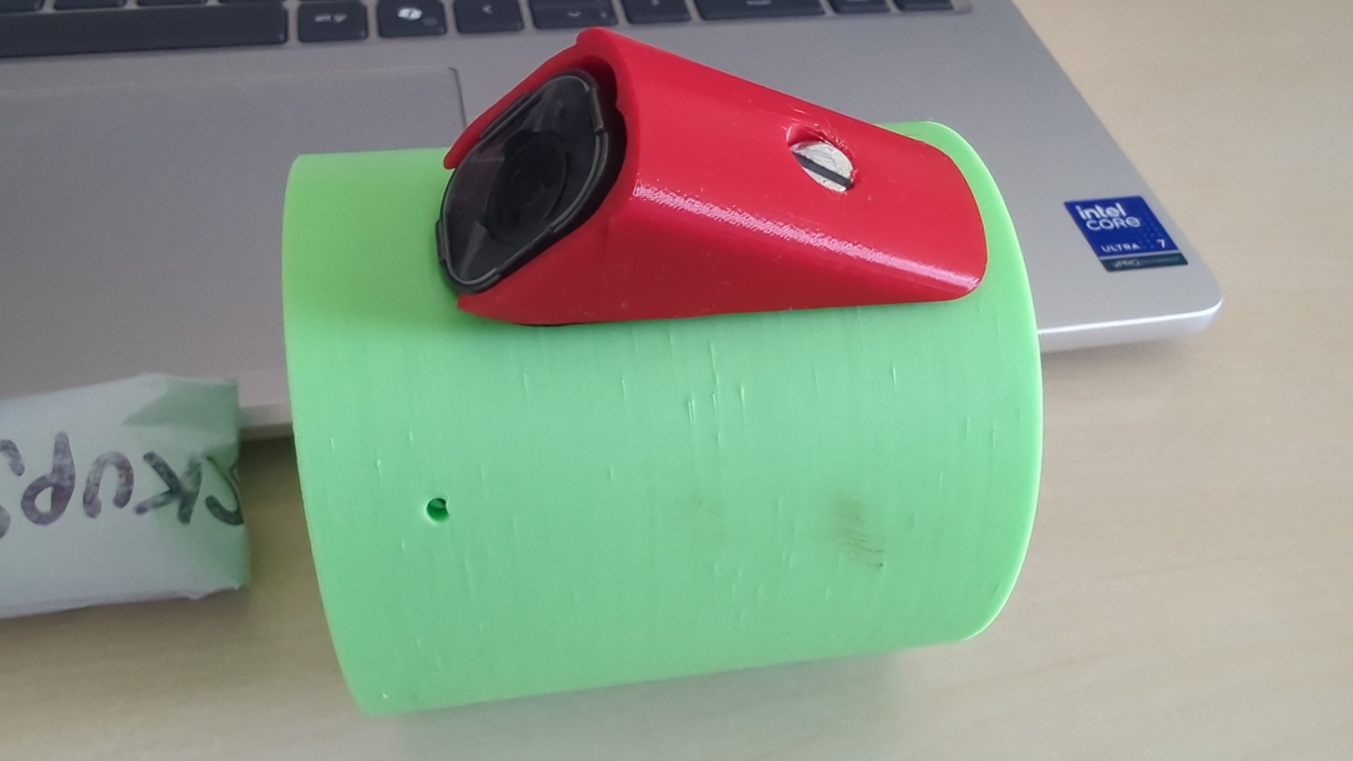
The controller lives in a 3D-printed rocket module — a green cylindrical housing with a red camera enclosure that presents the RunCam Thumb’s lens to the world.
The RunCam Serial Communication Protocol#
The RunCam Thumb Pro W doesn’t have a documented API, but it does speak a serial protocol — RCSP, the RunCam Serial Communication Protocol — over its UART pins, intended for flight controllers to trigger recording in the air. The hard part was figuring out the bytes.
There’s a partial community spec for RCSP, but the Thumb Pro W in particular behaves a little differently, so I ended up reverse-engineering it properly: six rounds of tapping the camera’s TX/RX lines and capturing the actual request/response bytes on the wire, then reconciling them against the spec until the frames matched. The result is a small, well-defined protocol:
- A request frame is
[0xCC][cmd][data…][CRC8]. - A device-info response carries the protocol version and a feature bitmask that tells you exactly what this camera supports (power-button simulation, WiFi button, mode change, the 5-key OSD navigation, and so on).
- Commands come back as ACK or NAK frames, with an error code on a NAK.
- Integrity is a CRC8/DVB-S2 checksum (polynomial 0xD5) on every frame, both directions.
The first thing the controller does on boot is send GET_DEVICE_INFO, cache the
feature bitmask, and from then on only use commands the camera actually
advertises.
The hardware#
The build is deliberately minimal:
| Part | Details |
|---|---|
| MCU | ESP32-C3 dev board with a built-in 128×32 SSD1306 OLED (I2C on GPIO5/6) |
| Camera | RunCam Thumb Pro W |
| Power | 1S LiPo (3.5–4.2 V) through a physical on/off screw switch |
| Camera link | UART1 at 115200 8N1 — GPIO3 TX → camera RX, GPIO4 RX ← camera TX |
| Status LED | the onboard GPIO8 LED |
The screw switch is the whole user interface for power. Flip it on and both the ESP32 and the camera come up; the ESP32 boots, finds the camera, and starts recording. Flip it off and everything stops. There’s no arm pin, no preflight sequence — I tried building those in and then simplified them all away, because for a screw-switch install they just added failure modes.
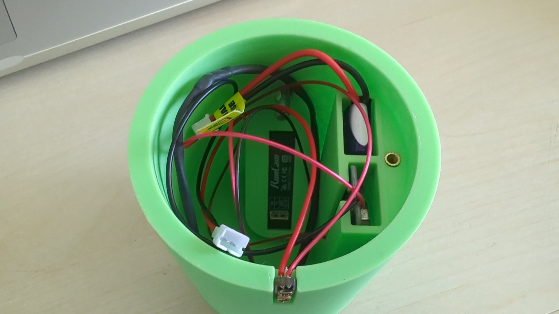
Inside the module: the RunCam Thumb camera (label centre), a purple LiPo, and the power switch, wired together in the bay. The ESP32-C3 controller sits in here too, out of shot.
The firmware is layered so the protocol, the camera, and the application logic never tangle:
Web UI (REST + WebSocket) ─┐
                           ├──► FlightController (IDLE / RECORDING)
Main loop ─────────────────┘          │
                                      ▼
                                 RunCamCamera
                                      │
                                      ▼
                          RunCamProtocol (CRC8 framing)
                                      │
                                      ▼
                              UART transport
The interesting part is thread safety. The ESP32-C3 runs FreeRTOS, and the
camera is a shared resource touched from two places at once: the main loop polls
it, and the web server’s request handlers command it. A FreeRTOS mutex
(camMutex) guards every access to the camera and the flight controller, and a
small RAII wrapper (CamLock) makes sure the mutex is always released even if a
handler throws. Without that, a web request landing mid-poll would corrupt the
serial exchange.
Underneath, the camera abstraction handles the messy reality of the protocol. Starting recording is a power-button toggle; stopping uses an explicit Stop action that NAKs if the camera is already stopped — which sounds like a bug until you realise it’s exactly what lets you resynchronise state when somebody has pressed the physical button. And because the ESP32 can’t see the camera’s button directly, the controller periodically polls the recording state while idle, so a manual press is detected and the displayed state stays honest.
A web UI over a WiFi access point#
When it boots, the ESP32 brings up a WiFi access point (RunCam-Controller).
You join it from a phone and open http://192.168.4.1/, and you get a
single-page web app — four tabs across the bottom:
- Status — a big badge showing IDLE or RECORDING, the elapsed recording time, and whether the camera is talking.
- Control — start/stop recording, capture a photo, and a button-simulation pad (power, mode, WiFi, and the d-pad for the OSD menus).
- Settings — the one setting that matters in the field: auto-start recording on boot, persisted to NVS so it survives power cycles.
- Device — the protocol version and the decoded feature bitmask.
The page updates itself over a WebSocket — recording time, state changes, and camera-comms status all stream in without polling. The HTML is generated at build time from source and stored in flash as a single PROGMEM string, so the device serves it without a filesystem.
Testing it without the hardware#
Embedded code is famously hard to unit-test, because everything wants to touch
the hardware. I didn’t want that, so the source is structured behind interfaces
(ICamera, IRunCamTransport, IPreferences) and guarded with #ifndef UNIT_TEST
around the ESP32-specific includes. The same .cpp files compile two ways: on
the device for real, and on the host against tiny mocks (MockTransport,
MockCamera, MockPreferences) for tests.
The result is 95 host-side tests that run on the development machine in
seconds — no ESP32, no flashing — covering protocol encoding and parsing, the
CRC8 against known vectors, the camera’s retry and state-polling behaviour, the
flight-state machine, and the settings store. make test and you know. That
caught a whole class of framing and state bugs long before they ever reached the
camera.
Building it with Claude Code#
Like the CYD control panel , I didn’t write this firmware by hand. I wrote a functional spec describing the camera, the protocol, and what the device should do, and then built it in phases with Claude Code — spec, implementation plan, code, host tests, then a code review pass. The reverse-engineered protocol frames, the threaded architecture, the WebSocket UI, the test harness — all described in plain language and iterated against the actual hardware. When a frame didn’t parse, I pasted the bytes I saw and the diagnosis came back. The barrier to a project like this has dropped dramatically; the spec and the debugging eye are now the scarce parts, not the typing.
Gotchas worth passing on#
The OLED has a COM offset. This particular 128×32 SSD1306 maps GDDRAM row 12 to physical pixel row 0. If you draw text at the y-coordinate you expect, it’s shifted halfway off the screen. Once you know, you just offset every y-coordinate by 12 — but you’ll waste an evening discovering it.
Account for bursty responses. When the camera NAKs, it can fire several response frames back-to-back. A naive “read until timeout after the first byte” drops the later frames. The transport extends its receive deadline by 200 ms after each byte, so a burst is read whole.
Camera settings remain a black box. RCSP defines commands to read and write camera settings (resolution, FPS, FOV…), but the Thumb Pro W’s setting byte IDs aren’t documented and I couldn’t probe them reliably, so settings access is deferred. Only auto-start-on-boot is configurable from the UI today; everything else is set on the camera itself.
Lessons learned#
A physical switch beats a clever startup sequence every time. I built arm-pin input, a five-minute auto-stop, and a preflight check, then deleted all of it for the screw-switch build. Each one was a state that could fail or hang; none survived contact with how the device is actually used.
Make the serial protocol observable early. The six rounds of on-the-wire capture were the difference between guessing at frames and knowing them. A logic analyser or even a raw byte dump is worth more than any amount of reading the (partial, contradictory) community specs.
And structure embedded code for the host compiler. The interfaces and the
UNIT_TEST guards cost a little extra typing up front and bought 95 tests that
run on my laptop. That trade is worth it for anything more complicated than a
blink sketch.
Resources#
- RunCam — the Thumb Pro W camera
- PlatformIO — the build/flash toolchain
- ESP32-C3 — the microcontroller
- ESPAsyncWebServer — the async HTTP + WebSocket server
- RunCam Thumb ESP32-C3 Controller on GitHub — the firmware, protocol notes, and host-side tests
- Turning a Cheap Yellow Display into a Home Assistant Control Panel — another ESP32 project, also built with Claude Code
- Ballistic Evaluation Motor Test 3 — the rocketry context this camera lives in