Building a Woordklok — A Dutch Word Clock
My wife wanted a word clock for the house for ages. There’s something deeply satisfying about a clock that doesn’t show digits at all — it just lights up the words: het is half drie. So when I came across a complete Dutch design for one, I finally had no more excuses.
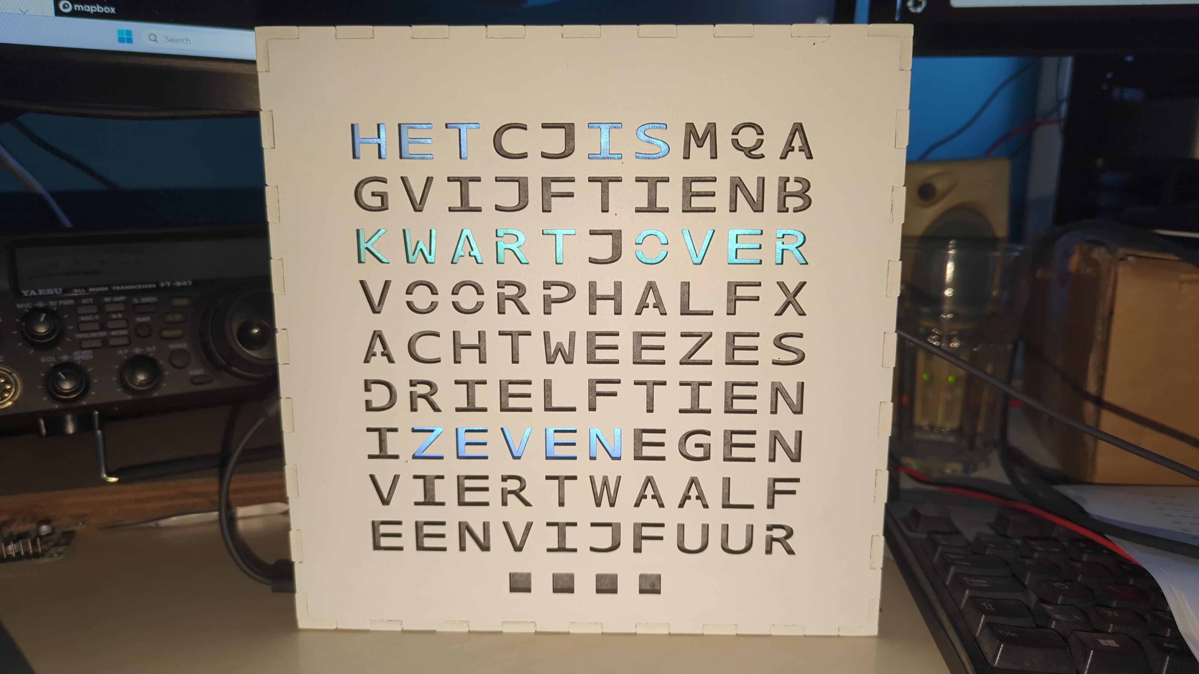
What’s a word clock?#
A word clock tells the time by illuminating groups of letters on a grid, so that the lit-up letters spell the time in words (rounded to five minutes). The face is a matrix of letters, and at any moment only the letters that form the current time are on. It’s a lovely bit of functional typography.
The design I built isn’t mine. It comes from DJO Amersfoort, who published a full “Maak een woordklok” tutorial — the laser-cut frame, the letter layout, the whole build. The firmware is a fork of vdham/wordclock on Bitbucket, written for a Wemos D1 mini (ESP8266) driving a WS2812B LED strip. So most of the heavy lifting was already done. My job was mostly assembling it — and then, as it turned out, fixing it.
The build#
Cutting the case#
The front panel and frame are laser-cut from the DJO SVGs. My K40 laser cutter’s bed is only about 300×200 mm, which isn’t quite big enough to do the full panel in one pass. So I split each panel design into two halves, cut them separately, and joined the halves back together afterwards. A bit of extra fiddling, but it beats finding a bigger laser.
The face is a 9×10 grid of letters cut into the front panel, with a WS2812B LED behind each cell. The clever part is the wiring: instead of ninety separate wires, the LED strip is one continuous chain snaked across the rows in a zigzag (an “S-vorm”, as the DJO instructions call it). Data goes in at the bottom-right corner — at the letter R — runs left along the bottom row, jumps up and runs right along the next row, and so on all the way to the top.
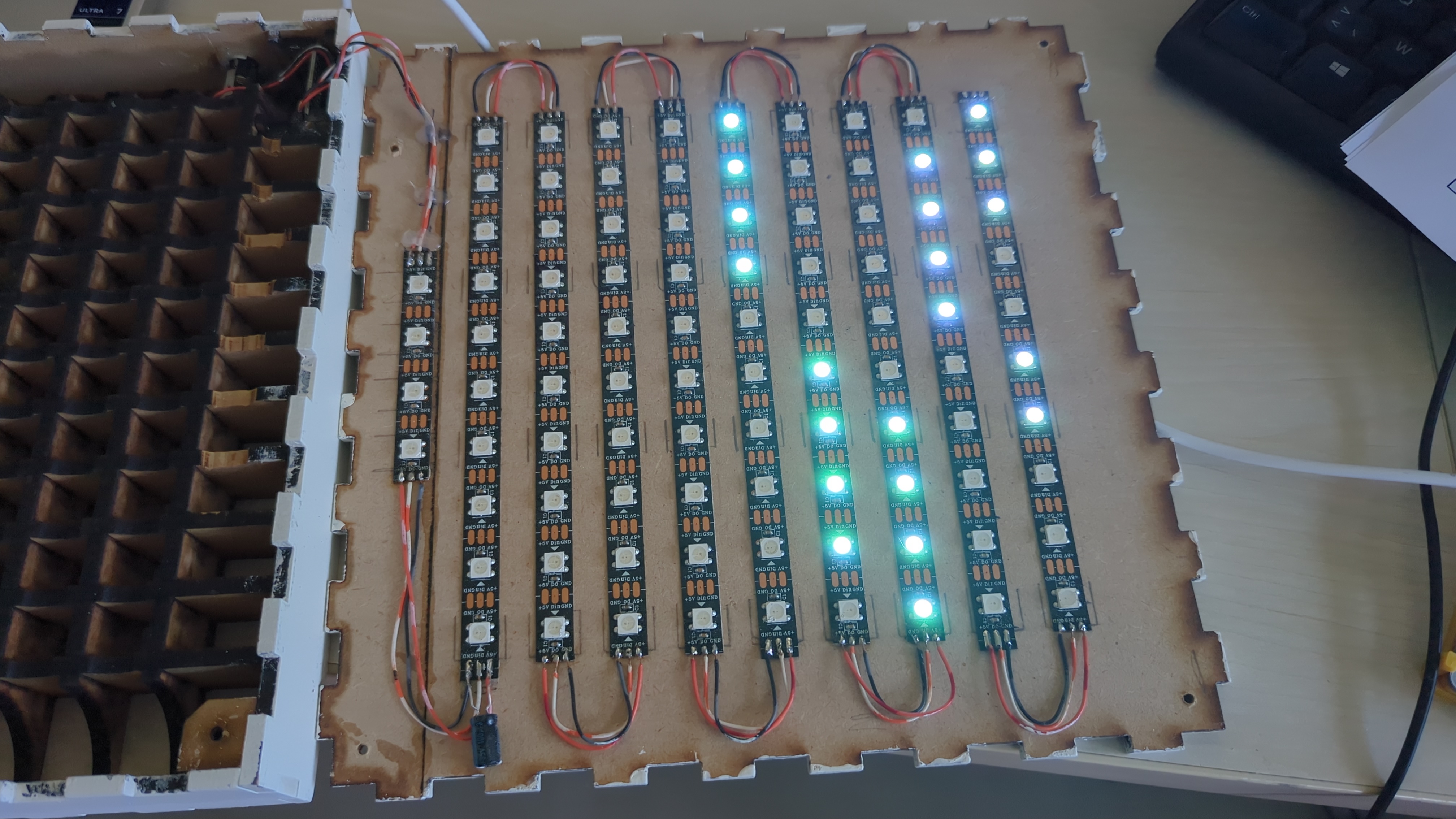
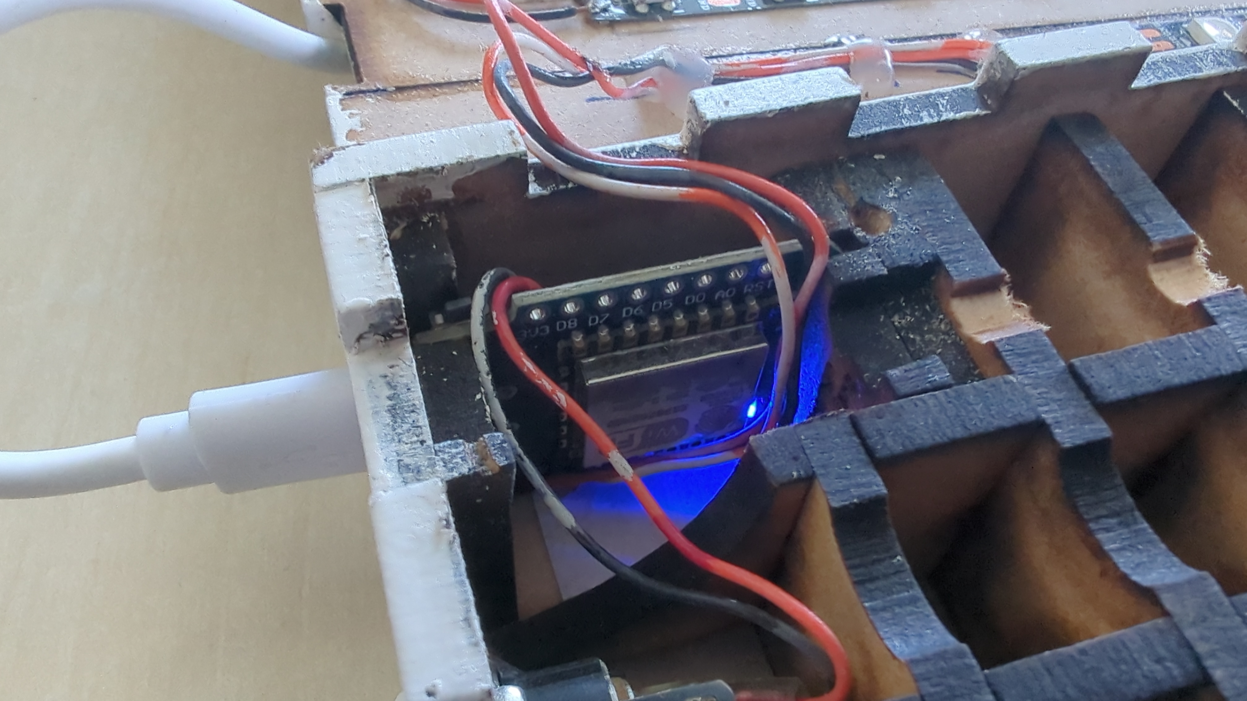
A Wemos D1 mini sits inside the frame. The design includes an LDR on the analog pin for automatic brightness — the firmware supports it — but I haven’t populated the LDR yet. Maybe later. NTP keeps the time with automatic daylight-saving, and there’s an OTA update port so I can flash new firmware over WiFi without having to open the case. The full strip pulls more current than USB can deliver, so it runs off a dedicated 5 V supply.
A few changes of my own#
On top of the original firmware, I made a handful of modifications:
- Minute LEDs. A word clock only resolves to five minutes, which always feels a bit coarse. So I added a short 4-LED strip at the bottom that shows the minutes within the current five-minute block — one dot per minute past the five.
- Stability. The original would occasionally crash and reboot the ESP8266. That came from three places: the NTP code blocked the main loop for over a second without yielding, the brightness sampling blocked it for another hundred milliseconds, and the LED refresh fought with OTA flash writes. A few targeted fixes — yielding in the right places, shorter sampling, and a guard that pauses the display during an OTA update — sorted it.
I published all of it on GitHub: steemandavid/woordklok .
And then it displayed the wrong time#
I flashed the firmware, and the clock lit up — but the words were gibberish. Letters that shouldn’t be on were on; letters that should have been on were off. My first instinct was that I’d broken something with my changes, so I diffed my version against the original code straight from the archive. Nothing in the display logic had changed — the word-to-LED mapping was byte-for-byte identical. The original map was simply wrong for my strip.
The thing about a word clock is that the word→LED mapping assumes one very specific physical wiring, and mine — built from the same DJO instructions — was wired differently. Rather than keep guessing, I added a tiny calibration mode that lights five specific LEDs in five different colours, and read off where each one physically landed. That gave the whole topology away in one look: my minute strip was the first thing in the data chain rather than the last, and the grid was offset and snaked in a way the original code didn’t expect. I rebuilt the map, pushed the fix over the air, and the clock has shown the right time ever since.
It was a good reminder: when hardware and software disagree, no amount of reading the code will tell you which one is right. You have to go and look at the hardware.
Lessons learned#
- Charge-only USB cables are the bane of embedded work. Two of the three
cables I tried were power-only; the board simply didn’t appear. Check with
lsusbbefore you assume your code is broken. - Calibration beats reverse-engineering. I spent a while trying to deduce the wiring from lit letters. Five coloured LEDs told me in seconds what an hour of guessing couldn’t.
- OTA is worth the setup. Once the firewall was told to allow the upload’s back-connection, flashing new firmware over WiFi became a one-liner — invaluable while debugging.
Resources#
- woordklok on GitHub — my fork, with the fixes
- DJO Amersfoort — “Maak een woordklok” — the original design, laser-cut files, and build tutorial
- vdham/wordclock on Bitbucket — the original firmware