VSCP toolchain
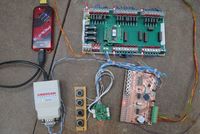 I’m experimenting with VSCP. The Very Simple Control Protocol is a simple but clever protocol implementation. Its creator made some of the same design choices I would have made, so it will be well-suited for my application as a home automation protocol. I’m not going to describe it here, you can read all about it on Wikipedia or on the VSCP website. Instead I will describe the set-up I have installed to learn VSCP and develop for it.
Hardware
This is what I use as stepping stones towards mastering VSCP:
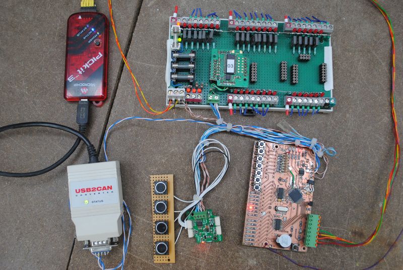
You can make out the following modules:
- The large module on the top right is a Antwerp module that sports a fair number of inputs of outputs.
- In the middle on the bottom is a tiny Antwerp module, with a 4 buttons perfboard attached for triggering button events.
- On the bottom right is a prototype of the Mespelare module that I’m developing for my home automation.
- On the top left is a PICkit 3 programmer that I use to develop firmware for my Mespelare module module.
- On the bottom left is an USB2CAN converter, which connects the VSCP bus to my computer over USB.
Software
MPLAB X IDE
I use the Microchip MPLAB X IDE, version: v2.05. As a compiler I am using the free C18 compiler by Microchip, which integrates nicely with the MPLAB X IDE.
Setting up the programmer
The PICkit is my favourite PIC programmer. Although Microchip managed to mess up a perfect product like the PICkit 2 when releasing the newer version PICkit 3, the newer micro-controllers are only supported by the PICkit 3.
There’s two ways you can use it with MPLAB:
- let MPLAB drive the PICkit 3
- use the stand-alone PICkit 3 with the auto import hex + write device feature
I’ll explain them both below, you choose which one you think is best. I recommend keeping everything in one integrated environment, so I let MPLAB handle the programming.
Let MPLAB control the PICkit 3
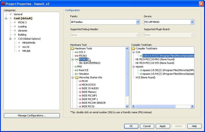
In MPLAB, open the File - Project Properties menu item, and click the Conf: [default] item from the Categories tree. Under the Hardware Tool tree you’ll see a PICKit3 item. If your programmer is connected to your computer, the two lights to the left of the text should be green.
Under this item you’ll also see an item mentioning the serial number of your programmer. While the intuitive choice would be to select the item with the serial number, thus allowing MPLAB to select the correct programmer in case you’d have multiple PICkit3’s connected, you need to select the PICkit3 item as per the screenshot below. Otherwise MPLAB won’t be able to use it.
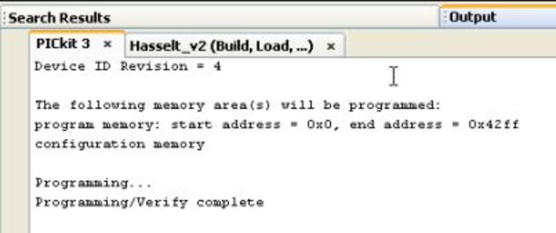
Now each time we select the Run - Run Main Project (F6) menu item, MPLAB will build our code and program it into our micro automatically. In the Output tab on the bottom of the MPLAB screen, a PICkit3 tab will appear which shows the programming progress.
PICkit 3 In-circuit programmer/debugger
One of the best features of the PICkit 2, its stand-alone and lightweight programming application, was discarded for PICkit 3. Luckily a beta application is available for the PICkit 3 in the forums.
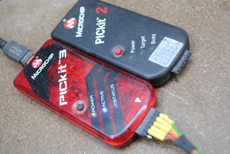
A great feature of the programming application is ‘Auto Import Hex + Write Device’, which looks for any changes in the hex file outputted by the compiler, and upon changes, automatically programs the PIC. This means that one simply has to hit ‘compile’ or ‘build’ in the compiler and the PIC is automagically programmed and ready running the new code after compilation.
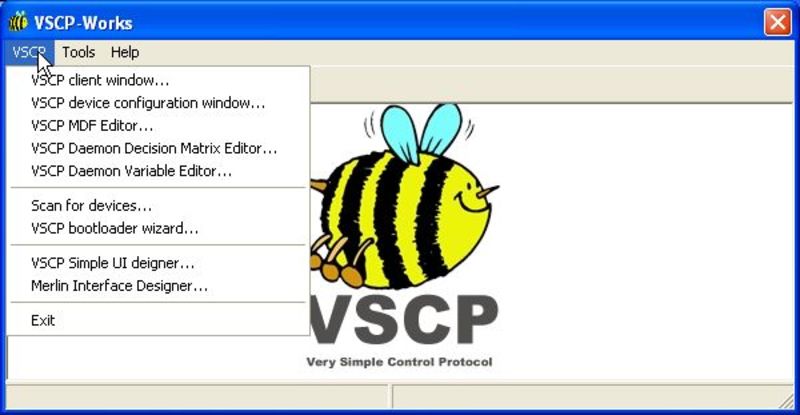
VSCP Works
VSCP Works version: 0.4.0.15. Download from the VSCP website
USB2CAN test application v1.0
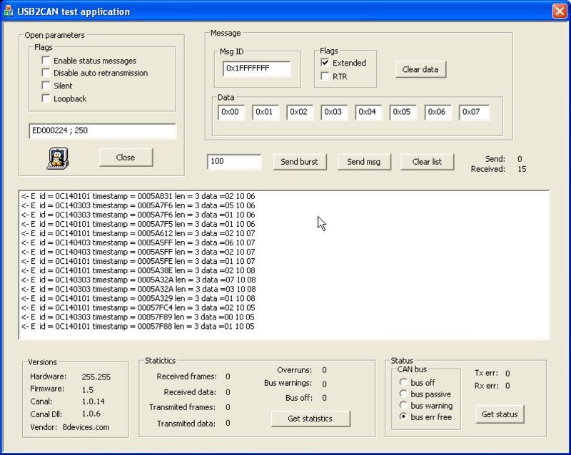
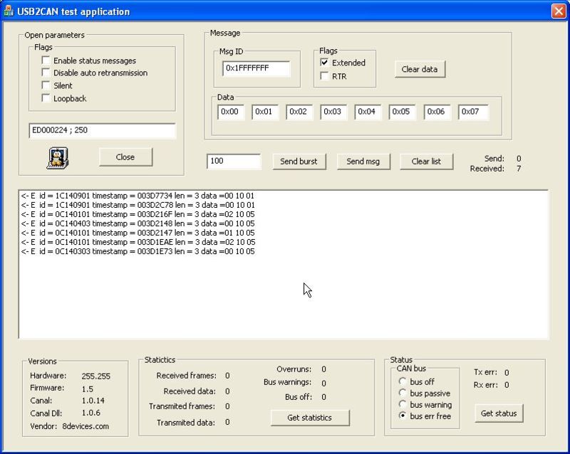
USB2CAN test application v1.0. Useful for testing if the USB2CAN converter is properly configured and sees packets on the bus.
When plugging it into a USB port, the LED on the USB2CAN converter will be flashing green-red. If you have typed in the correct address for the converter and hit the ‘Open’ button, the LED should turn steady green. This means that your converter is working correctly. It however does not mean that the bus speed is set correctly.
If packets are received by the USB2CAN converter, but they do not correspond to the bus speed which you set in the test application, the LED will go from steady green to blinking green. This means it cannot decode received packets, and you should change bus speeds.
The standard VSCP bus speed is 125 kbps. Kurt_sidekick is using 250 kbps for his Hasselt and Antwerp modules.
If the LED is blinking green than it could also mean that you have no devices on the bus (bus not connected).
If you see packets in the monitor window below the ‘Open’-button then you know your VSCP bus is working. Obviously you will only see packets if you have active modules on the bus which send them. VSCP modules will automatically send a node heartbeat packet every once in a while.
Setting up a VSCP environment
This is the work-flow I followed for troubleshooting and testing my VSCP environment. I was lucky enough to be provided 2 VSCP modules by kurt_sidekick, so I could start from a known-to-be-working VSQCP bus.
USB2CAN converter
-
Install the latest USB2CAN drivers for your OS.
-
run the USB2CAN test application v1.0 to make sure that the USB2CAN converter is properly set up and that it can see packets on the bus. Set the correct module serial number and bus speed.
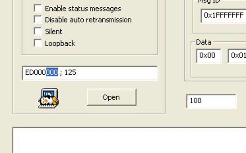
The Hasselt and Antwerp modules use 250kbps instead of VSCP’s standard 125kbps. The USB2CAN module expresses bus speeds in kbps, so be careful to only enter ‘250’ or ‘125’ instead of ‘250000’ or ‘125000’.
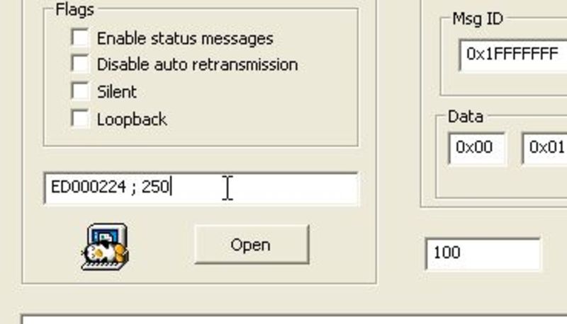
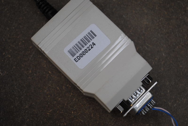
The converters’ serial number is printed on the back of the module. It is used as a hardware address so that the software application finds and connects to the correct hardware. I guess this means you can connect multiple USB2CAN converters to a single computer, although I haven’t tried this.
Hit the ‘Open’ button below the address/speed settings. If all is well then the LED on the USB2CAN converter will go from steady red to solid green, and the ‘open’ buttons’ text should change to ‘close’. If packets are passing on the bus you should see them show up in the monitor field.
VSCP Works
These steps will install, configure and test VSCP Works:
-
Install: download the latest version from vscp.org and install it.
-
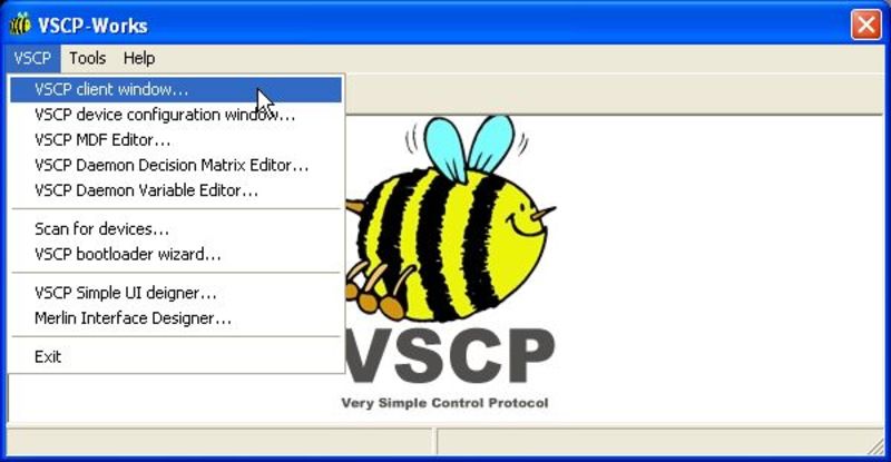
Open the client window:
-
VSCP Works will pop up a windows asking you to select the interface you are using to connect to the bus. Select ‘CANAL: USB2CAN’, but do not double-click or click ‘OK’ yet. Instead we will be configuring the interface first, so select ‘Edit’:
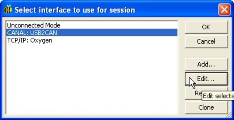
-
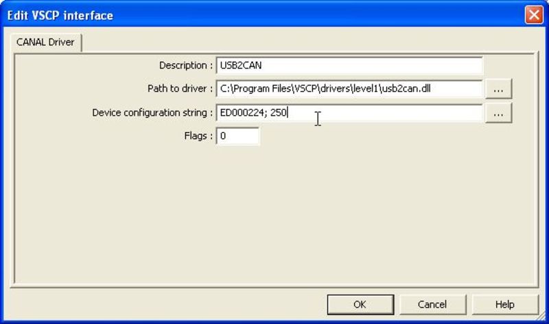
Enter the correct path to your USB2CAN driver. You can download this driver (USB2CAN.dll) from the website. The driver is also included in the test application download, so you can copy it to the VSCP Works driver folder. Also set the correct address for the converter, and the correct bus speed.
-
If your setup is working, you should be greeted with a Client Window which shows events on the bus scrolling by.
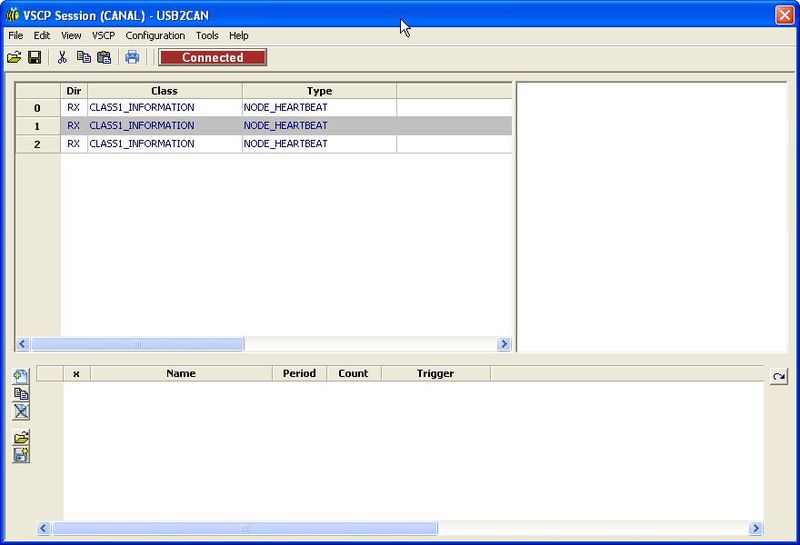
Congratulations! You now have a working VSCP environment!
Programming environment - PICkit 3
To enable development of modules for VSCP, we’ll take it a step further and set up a development environment. I am developing for Microchip PIC, so this information will focus on this device family.
I like the PICkit stand-alone programming environment, so I am using that to program the PIC instead of the integrated IDE.
-
Download and install the PICkit 3 application
- Check communication with the programmer
-
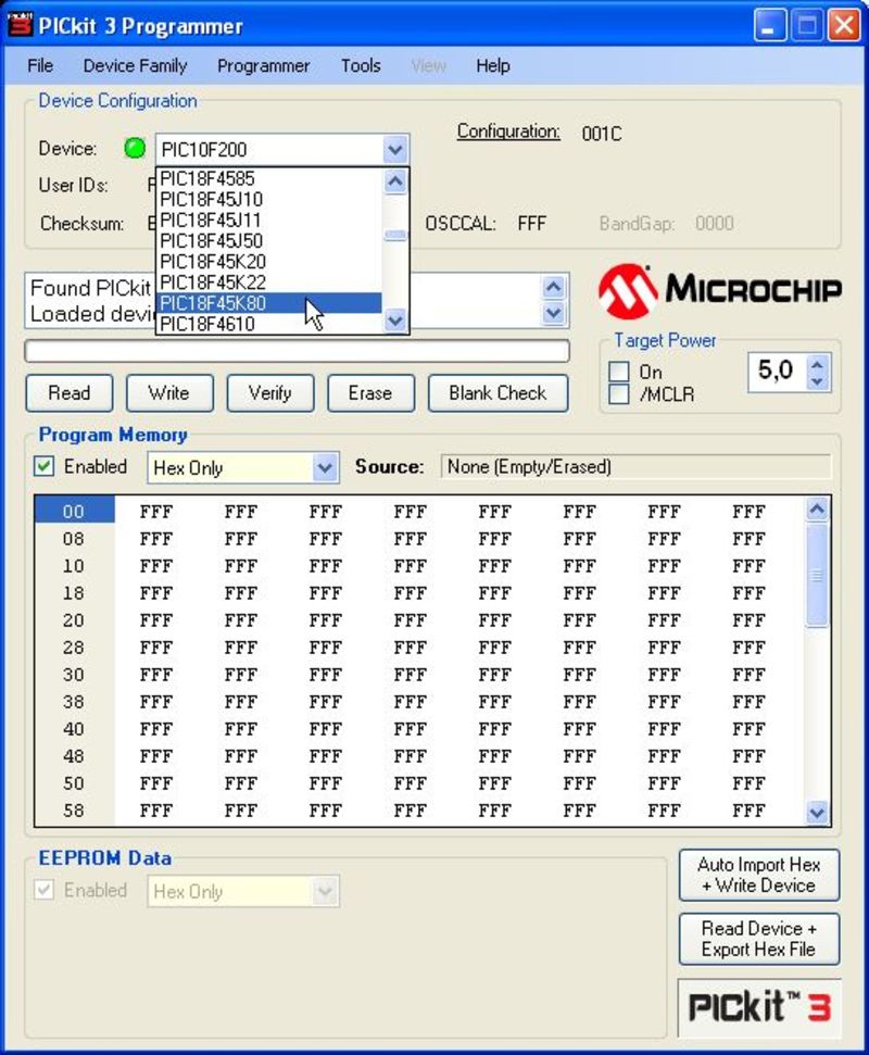
Select the correct device to program. In my case I am using a 1845K80.
-
Check if the programmer is communicating with the PC. It should say “Found PICkit 3, SN: BURxxxxxxxxx”.
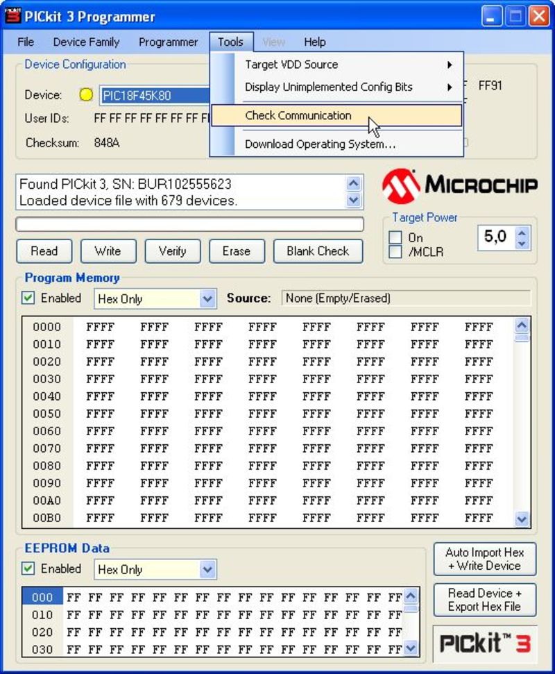
-
- Check communication with the the target board by reading the PIC
- Click the ‘Read’ button and you should see “Reading device .. Program.. EEPROM.. Config.. User…”. The program memory should also no longer be filled with just “FFFF” values, but should display the data you just read from the PIC.
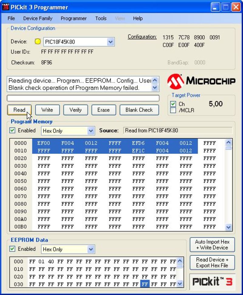
- Click the ‘Read’ button and you should see “Reading device .. Program.. EEPROM.. Config.. User…”. The program memory should also no longer be filled with just “FFFF” values, but should display the data you just read from the PIC.
Your PICkit 3 programming environment is now set up correctly.
If the above doesn’t work:
- check if you have selected the correct device
- check your connection between the PICkit and the PIC you are trying to program
Programming environment - MPLAB X and C18 compiler
- Go to the Microchip website
- Download and install the MPLAB X environment
- Download and install the C18 compiler
Programming environment - Source code
Download the source code from GitHub if you want to work on an existing project.
In the next article we’ll take this development environment and try to compile the Hasselt code for the first time.
Serving up MDF files
When reading the registers from a node, VSCPworks will fetch the MDF file from a URL which is defined in node itself. To allow VSCPworks to download these files, we’ll need to set up a web page somewhere. The easiest way is to run a small webserver on a local machine in the network, and have it serve up a folder where we can drop the MDF files. I am using Mongoose, a lightweight and simple web server.
First we’ll create a folder on a local machine where we’ll store our MDF files.
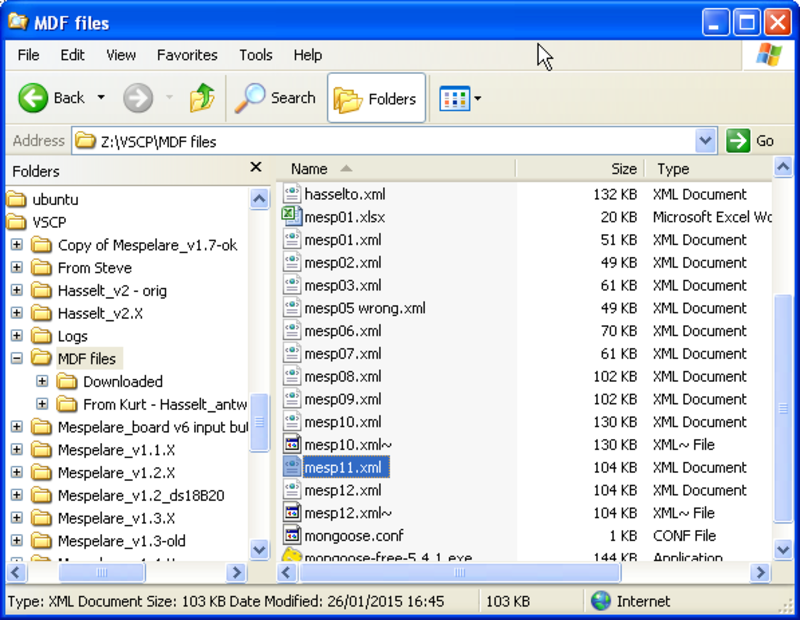
Now we download the Mongoose executable into this folder and run it. A Mongoose icon will appear in the task tray.
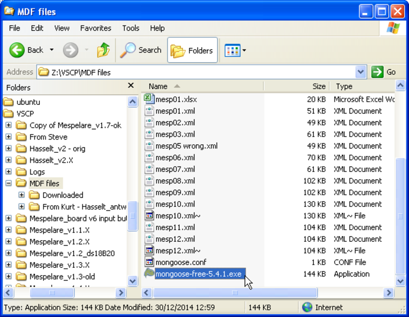

Right-clicking it opens an options menu. In this menu we’ll need to specify the folder which we want Mongoose to serve up. By default Mongoose will use the folder where it was started from, and it will use port 8080.
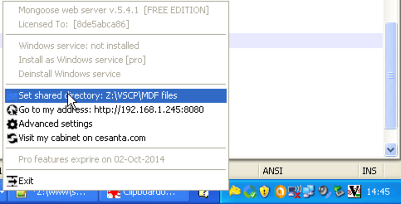
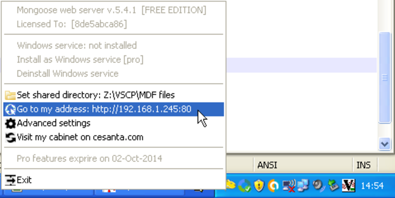
We can change these default start-up values by creating a configuration file in the folder Mongoose was started from, mongoose.conf. In this file we can specify the folder to serve, the port Mongoose listens to etc. In my case I want the server to listen on the standard HTTP port 80, so I use this config file:
# Mongoose web server configuration file.
# For detailed description of every option, visit
# https://github.com/cesanta/mongoose
# Lines starting with '#' and empty lines are ignored.
# To make a change, remove leading '#', modify option's value,
# save this file and then restart Mongoose.

# access_control_list
# access_log_file
# auth_domain mydomain.com
# cgi_interpreter
# cgi_pattern **.cgi$|**.pl$|**.php$
# dav_auth_file

#document_root Z:\VSCP\MDF files

# enable_directory_listing yes
# enable_proxy
# extra_mime_types
# global_auth_file
# hide_files_patterns
# hexdump_file
# index_files
index.html,index.htm,index.shtml,index.cgi,index.php,index.lp

listening_port 80

# ssi_pattern **.shtml$|**.shtm$
# url_rewrites
We can now test if the web server works by right-clicking the Mongoose task tray icon and selecting the Go to my address option. The URL which Mongoose is serving should be shown.
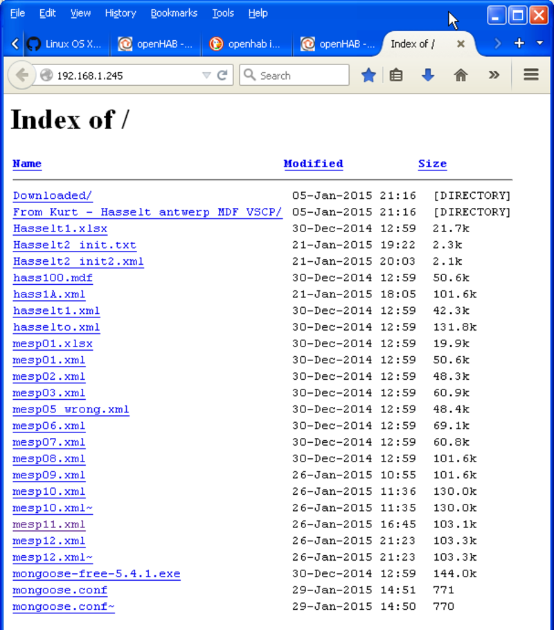
The served page should now open in the default web browser, and you should see the MDF files which we put in to the folder earlier.
Now we need to tell VSCPworks which file to fetch for which node. This is done in the node’s firmware itself. In the source code should be a variable that defines the location of the MDF that goes with the node. VSCPworks will read this variable through the standard registers 185 to 216, and use it to fetch the file.
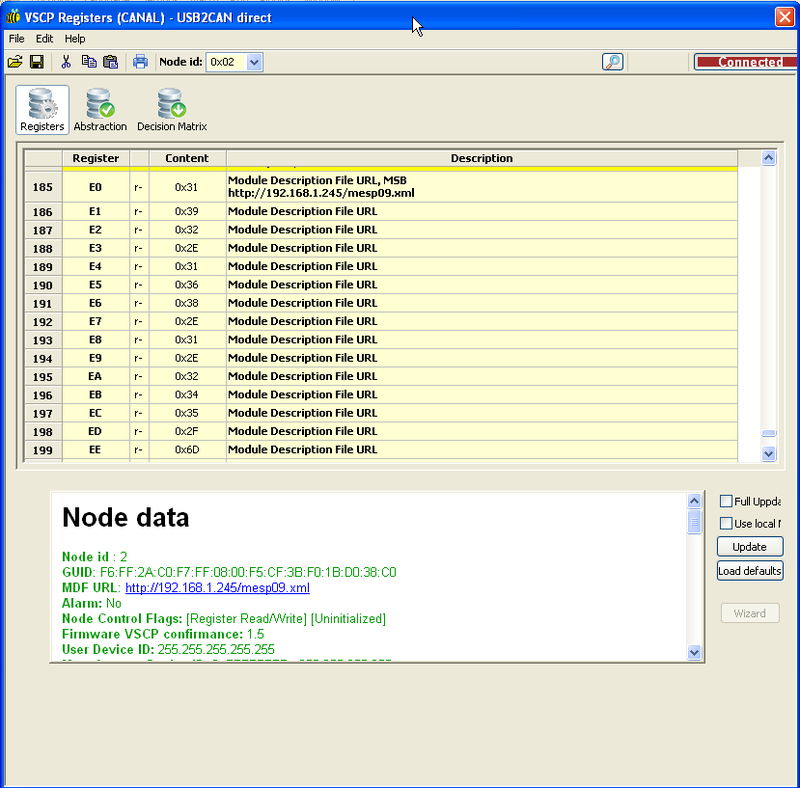
For the Mespelare node, the MDF files are served from a local machine on my LAN, and the proper MDF is mesp11.xml (for Mespelare 1.7 firmware).
// The device URL (max 32 characters including null termination)
const uint8_t vscp_deviceURL[] = "192.168.1.245/mesp11.xml";
Do note that we do not have to add the port :80 after the IP address, since 80 is the standard port.