Running the Mespelare firmware
 In the previous articles we’ve set up our tool chain and compiled source code for the first time. In this article we’ll be modifying the source code we’ve downloaded to fit the Mespelare board. We’ll be taking baby steps here so bear with me.
This article is a draft and is not finished yet. Proceed at your own peril.
First another check…
Before we proceed we’ll run another check on our source code and build environment by building the downloaded code, programming it into our Mespelare board and verifying that it runs.
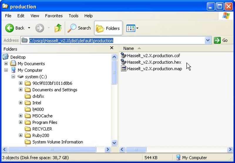
If you build the code (MPLAB menu “Run” - “Build main project”), you’ll see a set of files appear in the /dist/default/production folder. We’ll proceed to program the hex file into our Mespelare board.
I suggest you open this folder and delete the files that are already there. Now rebuild the project and see if the files are being output by MPLAB X.
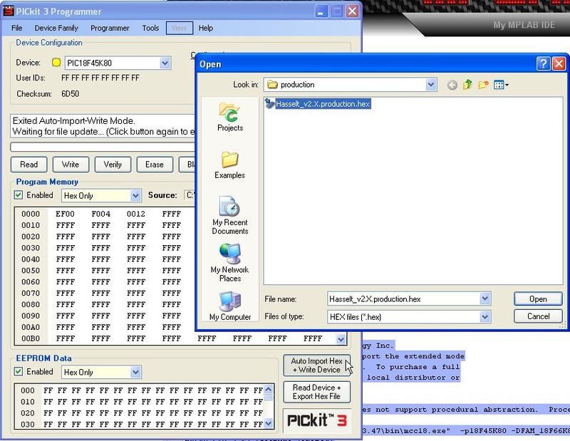
Now program them into the Mespelare board. I use the “Auto Import Hex + Write Device” which makes the programmer automatically program the PIC every time we make a code change and build.
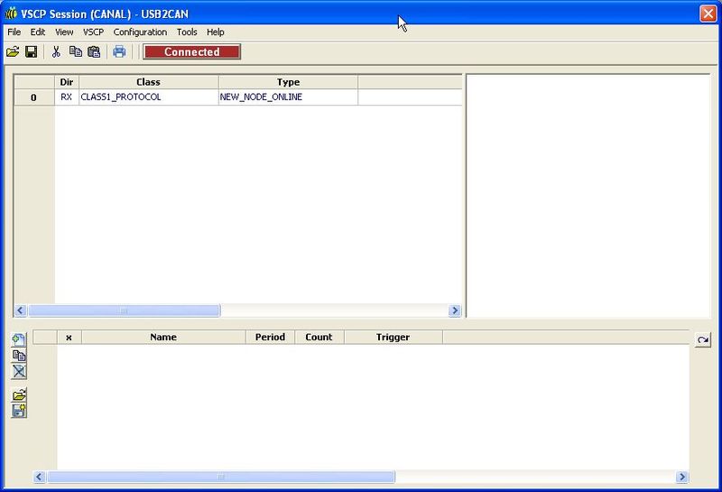
Once the programming is done, you should see a NEW_NODE_ONLINE event on the bus (check with the VSCP-Works Client window). LED 2 should be blinking as the new node (our Mespelare board) is acquiring an address on the bus. (Do mind, it only blinks right after you’ve programmed the board, not after every power-up.)
If you press button 1 you should see a BUTTON event on the bus.
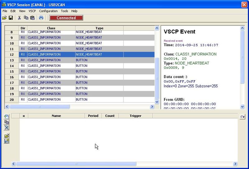
So now we know that our downloaded (Hasselt) code has been compiled, built and programmed properly.
Adapting the code to the Mespelare hardware
The Mespelare board is not very much different from the Hasselt board, but still we’ll need to make some changes to the Hasselt code to allow it to run correctly on the Mespelare board.
Pin assignments
Let’s start with looking at the board files for Hasselt (and Antwerp - format is CADsoft Eagle). The pins are connected like this:
- INP1: RC7
- INP2: RC1
- INP3: RC2
- INP4: RC0
- INP5: RC6
- INP6: RC5
- INP7: RC4
- INP8: RC3
- OUT1: RB0
- OUT2: RB1
- OUT3: RB5
- OUT4: RB4
- OUT5: RA3
- OUT6: RA2
- OUT7: RA1
- OUT8: RA0
- INIT SWITCH: RB7
- STATUS LED: RA5
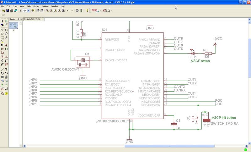
The Mespelare board has a different pin-out:
- INP1: RD7
- INP2: RB0
- INP3: RB1
- INP4: RB4
- INP5: RB5
- INP6: RB6
- INP7: RC6
- OUT1: RE1
- OUT2: RE2
- OUT3: RC0
- OUT4: RC1
- OUT5: RC2
- OUT6: RD0
- OUT7: RD1
- LED1: RB7
- LED2: RA0
- LED3: RA1
- LED4: RA2
- LED5: RA3
- LED6: RA5
- LED7: RE0
- MISC_LED: RD3
- STATUS LED: RD6
- BUTTON: RC7
- BUZZER: D2
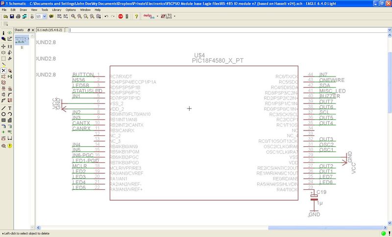
This means we’ll have to change the code that maps the software labels to the correct hardware pins. We’ll re-use the Hasselt labels, and just change what pins they map to. This way we do not have to change the rest of the code for now. Obviously we’ll have to dig in later because the Mespelare module has more pins (LEDs, buzzer, extra LED), which we’ll need to add to the code before these will function. But for the sake of baby steps, let’s first only change the mappings.
The mappings from hardware pin to software label live in the file “VSCP_node_defines.h”. We will define our pins like this:
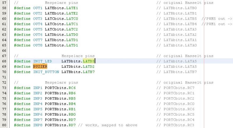
(the original Hasselt definitions have been commented out but kept for reference)
As you may have noticed, we’ve taken some shortcuts here: the 8th input and output pins (which are not available on the Mespelare module) have been mapped to the same pins as input and output 7 respectively.
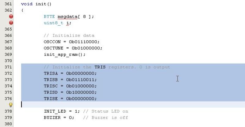
Next let’s set the correct TRIS registers in the init()-function in main.c:
// Initialize the TRIS registers. 0 is output
TRISA = 0b00000000; // Hasselt: 0b11000000;
TRISB = 0b01111011; // Hasselt: 0b11001100;
TRISC = 0b01000000; // Hasselt: not set
TRISD = 0b10000000; // Hasselt: 0b11111110;
TRISE = 0b00000000; // Hasselt: not set
Setting the correct MDF file location
Over the network
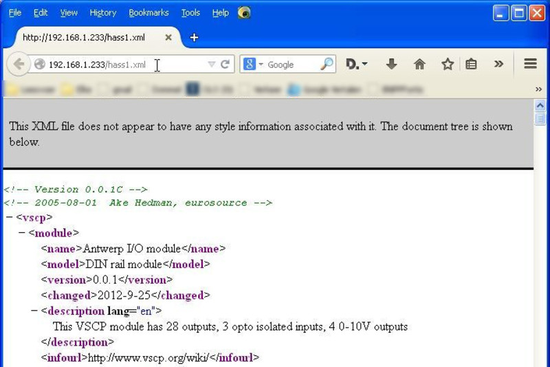
The location of the node’s MDF file is hard coded in the source code. You can find it in the main.c-file:
// The device URL (max 32 characters including null termination)
const far rom uint8_t vscp_deviceURL[] = "192.168.1.223/hass1.xml";
For VSCP to be able to access the file, it will have to be available at this location for download. I use Mongoose as a local web server and put the XML file in the root of the path that is served by Mongoose. (Example Mongoose config file)
Let’s first check if we can access the file at this address in a web browser. I suggest you copy-and-paste the URL straight from the source code into the browser’s address bar to avoid any typos.
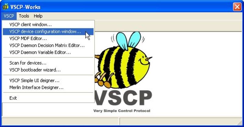
Now start the VSCP device configuration window from the VSCP-Works menu.
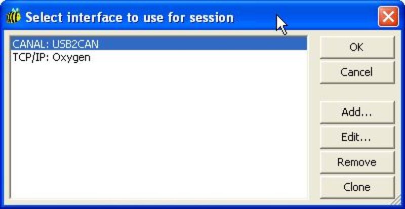
Select the correct interface (USB2CAN).
Now select the correct node. In my case, the Mespelare board is on address 0x02.
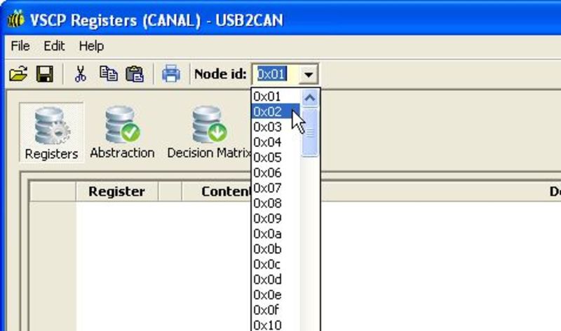
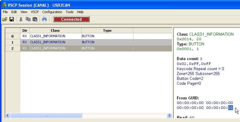
In case you do not know the address of the node, you can check that in the client window by generating an event (e.g. a button event), selecting that line and looking at the GUID.
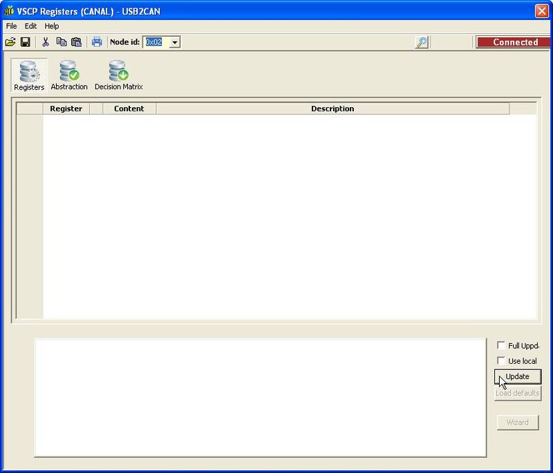
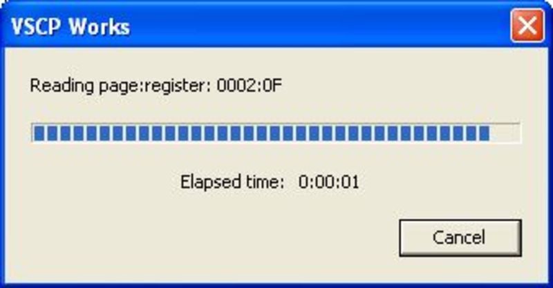
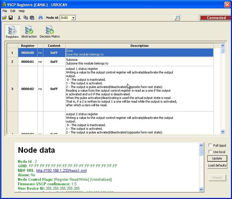
In the device configuration window, hit the ‘Update’ button. You’ll see VSCP reading from the node’s registers.
If the registers have been read correctly, you should see something like this:
Local MDF file
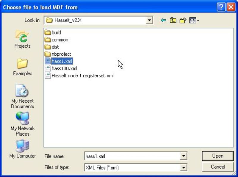
If you can’t get the MDF to load over the network, an alternative is to load it from a local file. Tick the “Use local MDF” check box above the “Update” button. When you click the “Update” button a pop-up window “Choose file to load MDF from” will appear. Select and open your MDF in this window.
Setting the registers
Now let’s attempt some updates to the registers. Now would be a good moment to read up on some of the general VSCP concepts such as the Decision Matrix, mask/filters etc. Check my post Getting started with VSCP for links to this information.
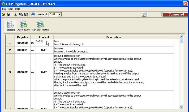
Double click the 0xFF on the first line, and modify it to 0x01.
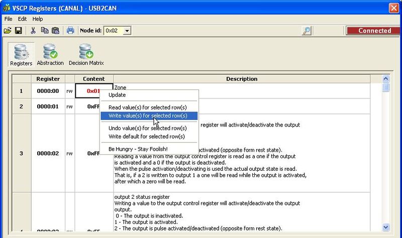
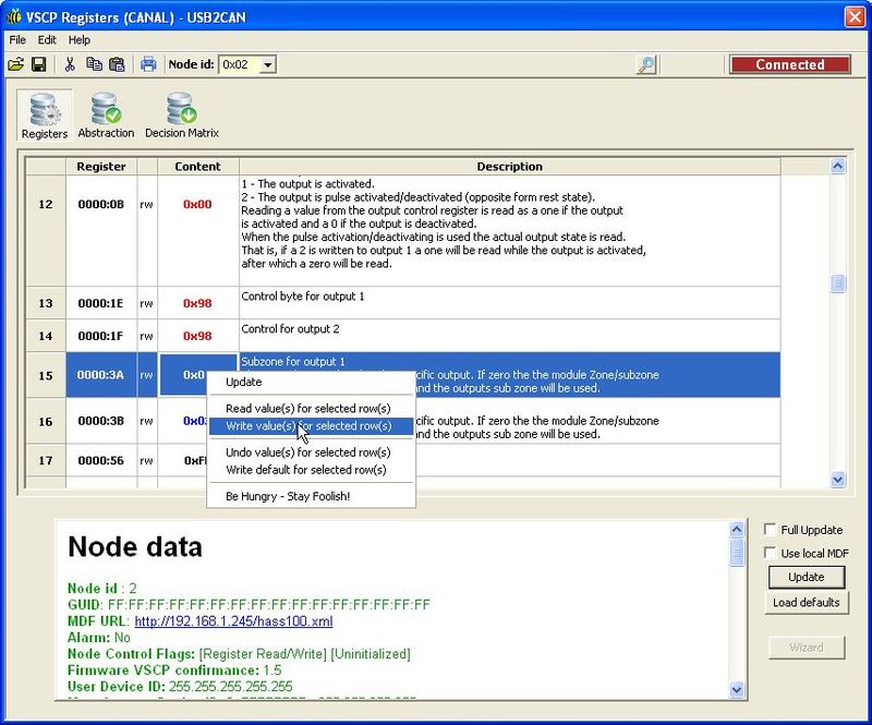
Right-click that line and select “Write value(s) for selected row(s)”. You should see a write screen flash by.
Close the device configuration window and re-open it. Select the correct interface and node address again, and hit the ‘Update’ button (like we did before). The 1st register should now read the value we modified, 0x01.
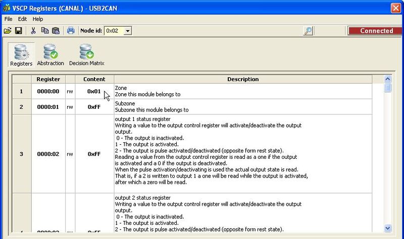
Let’s set the registers the same as our known-good Hasselt module. (Here’s a copy of the registers)
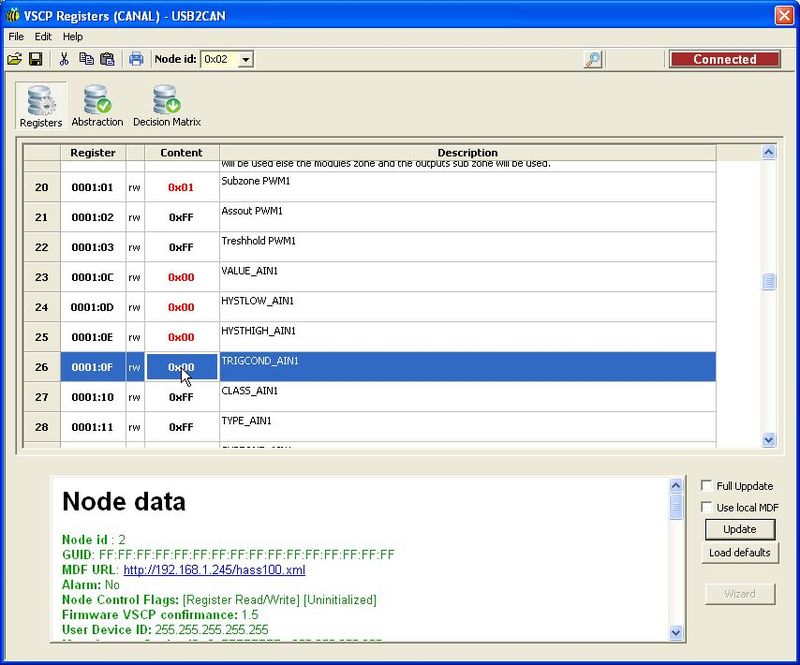
Write the modified lines by selecting a line, right-clicking it and selecting “Write value(s) for selected row(s)”. The modified value’s colour should change from red to blue. I select and write the modified lines one by one since I haven’t found a good way to write them in batch.
Let’s save our hard work into a register file so we can import it later if needs be. From the “File” menu, select “Save registers to file”.
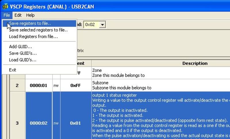
You can choose to save as a .reg file or as XML. Choose a file name and select save.
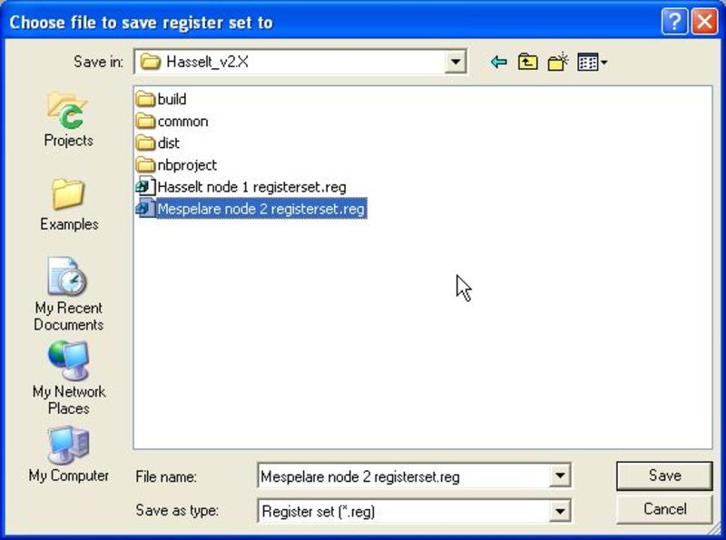
Side note: if VSCP-Works, at a later stage, fails to re-import the register file we just saved, it is because some versions of the Hasselt MDF contain 4 hex values with a Unicode multiplication sign instead of a regular ASCII ‘x’. If you open the file with a good text editor (I use Notepad++) and do a search-and-replace then VSCP will be able to import the file.
Register updates
Now let’s make some register updates to see if our module responds to them.
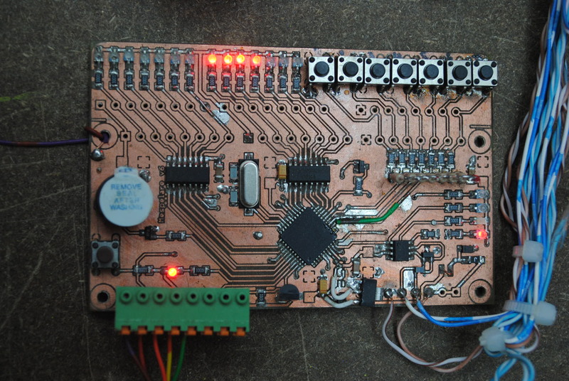
This is what the module looks like when it is powered on and has set its nick.
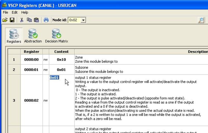
Let’s see if we can change the status of some of the outputs. In the device configuration window, scroll to the line that shows the “output 1 status register”. Set the content of this register to 0x01.
Once you right-click that line and select “Write value(s) for selected row(s) you should see the LED for output 1 come on. Subtle difference, isn’t it? But progress nonetheless.
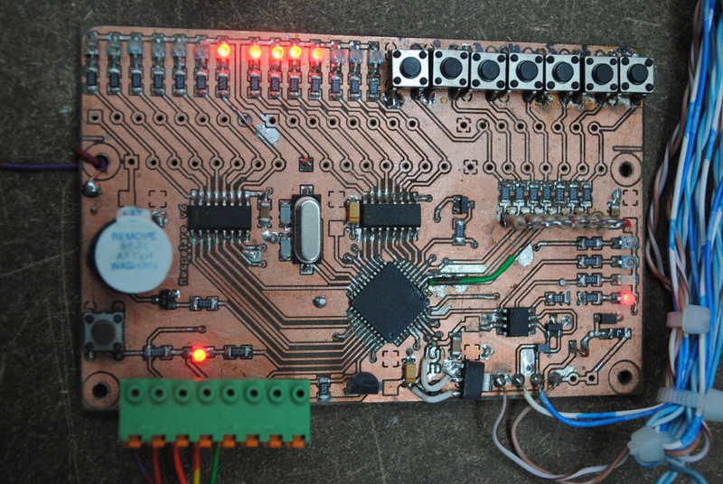
Now toy around with the values for the other registers. Do remember that:
- we have only 7 outputs defined (so no use setting registers 9 and 10)
- we mapped output 8 to the output 7 pin in the VSCP_node_defines.h file (so LED 7 should respond to changes in both registers 7 and 8)
In the next article, we’ll be playing with the Decision Matrix so we can make the module respond to events on the bus.
Resources
- Hasselt DIN node 3 registerset 20140928.reg
- Mespelare node 2 registerset 20140928.reg
- Hasselt node 1 registerset 20140928.reg
- Mespelare GitHub repository