Mespelare VSCP node
 The Mespelare node is a VSCP board based on the Hasselt board by kurt_sidekick, used to read a Niko 6-way potential-free button set, and control it’s 6 indicator LEDs as well as 6 outputs (teleruptors).
It is intended to serve as a general base node for further development of custom functionality, without each time having to re-invent the wheel. To reach this goal most processor pins are broken out to pin headers, which either connect to the Niko 6-button switch and teleruptors, or are populated with pin headers so another board can be piggy-backed onto the base node (Arduino shield-style). Using the same base board to build new applications on offers the following advantages:
- A stable, well-debugged and known-working base platform
- The possibility to do bigger board production runs
Features
The Mespelare VSCP board has the following features.
7 inputs
6 inputs are intended to read the button-presses on the Niko 6-way push-button set. A seventh input was added just because we can, and to provide an extra input in case the base board is used in another application. The inputs are filtered using a low pass filter on each channel to prevent HF interference from reaching the microprocessors’ inputs.
2 x 7 outputs
6 outputs are in are intended to control the LEDs that are integrated in the Niko 6-way push-button set. A seventh output was added just because we can, and to provide an extra output in case the base board is used in another application.
6 outputs are in are intended to control up to 6 teleruptors. A seventh output was added just because we can, and to provide an extra output in case the base board is used in another application.
One wire interface
The micro-controller’s OneWire interface was broken out onto a pin header.
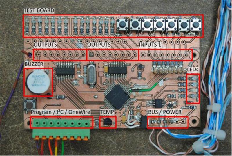
On board peripherals:
- 1 button (which can be used as a VSCP button or for troubleshooting)
- 1 LED (mainly for troubleshooting purposes)
- Buzzer (mainly for troubleshooting purposes)
- A footprint for a DS18B20 temperature sensor.
On board status LEDs:
- RX (CAN bus)
- TX (CAN bus)
- Power status
- Status (VSCP)
Power supply
- On-board Microchip MCP1804 power regulator
- 6.3-28V input
- 5V 150mA output (the low power output means extension boards will require a separate regulator)
- Protected by a 200mA poly-fuse and crowbar circuit
- Filtered against power rail noise
- Proper decoupling for all chips on the board
CAN bus
- A properly filtered, protected and impedance-matched bus connection
- Controlled by a Microchip MCP2551 bus interface chip
Expansion / ICSP header
A single “expansion/ICSP header” combines the ICSP signals with a OneWire and I²C bus. The order of the first 5 pins on the header are compatible with the PICkit pin-out.
PCB mounting
4 mounting holes in the corners for easy mounting, M3 size.
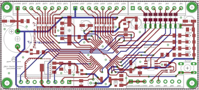
Printed circuit board
Design criteria
- Possible to produce at home using a photo-transfer process, so that the board can be prototyped and tested at home. This means:
- PCB size must not exceed Eurocard dimensions
- a minimum of via’s
- no tight spacing of components and tracks
- a minimum of through-hole soldering on the top layer
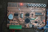
- Addition of an integrated set of LEDs and buttons on the first prototype
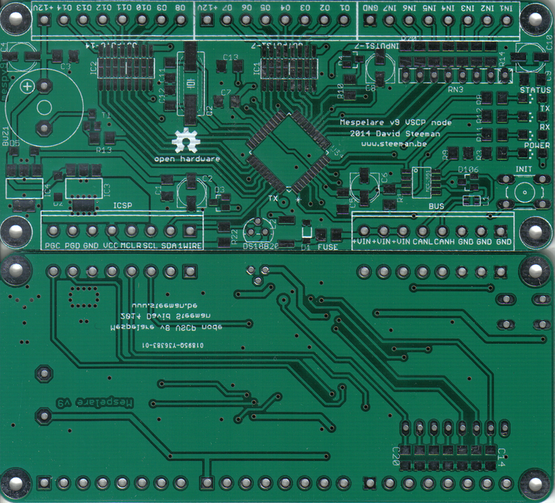
I had the PCB professionally produced at SeeedStudio, it cost only 1.83€ per board for 30 boards shipping included.
Testing
Until we write custom firmware for this node, we’ll be testing the node bit by bit.
Quick test
Although the firmware for the Hasselt node isn’t compatible with the pin-out used by the Mespelare node, some functionality does work. If you load the Hasselt hex file the node will be visible on the bus. Buttons 1 will send events as well.
Hardware tests
I use these detailed test programs to check separate parts of the hardware to see if they function correctly. Download a zip with the source code and pre-compiled HEX file.
- Blink-a-led: generates a buzzer tone at start-up, and then randomly blinks all LEDs on the board
- Button & leds: each press of the init button toggles each LED on the board, one after the other
- Inputs: toggles the corresponding outputs when pushing a button
- CAN toggle: puts a 50Hz square wave on the CAN bus pins
- DS18B20 Onewire: beeps the beeper when a temperature change is detected
- DS18B20 Onewire serial: outputs temp value to serial (9600, 8n1, no flow), and beeps the beeper when a temperature change is detected
- Button: sounds the buzzer when the misc button is pressed (board revision v6 only)
Downloads
Source code: see the article Mespelare VSCP firmware - first compile